
Some time back, I had a fair amount lot of free time. I spent the time working with a friend in the evenings to create my own LED cube from scratch. It was actually quite a bit of fun, the electronics was not overly complicated with most of it being done by a raspberry pi. It was fun to see both the hardware and the software side by side.
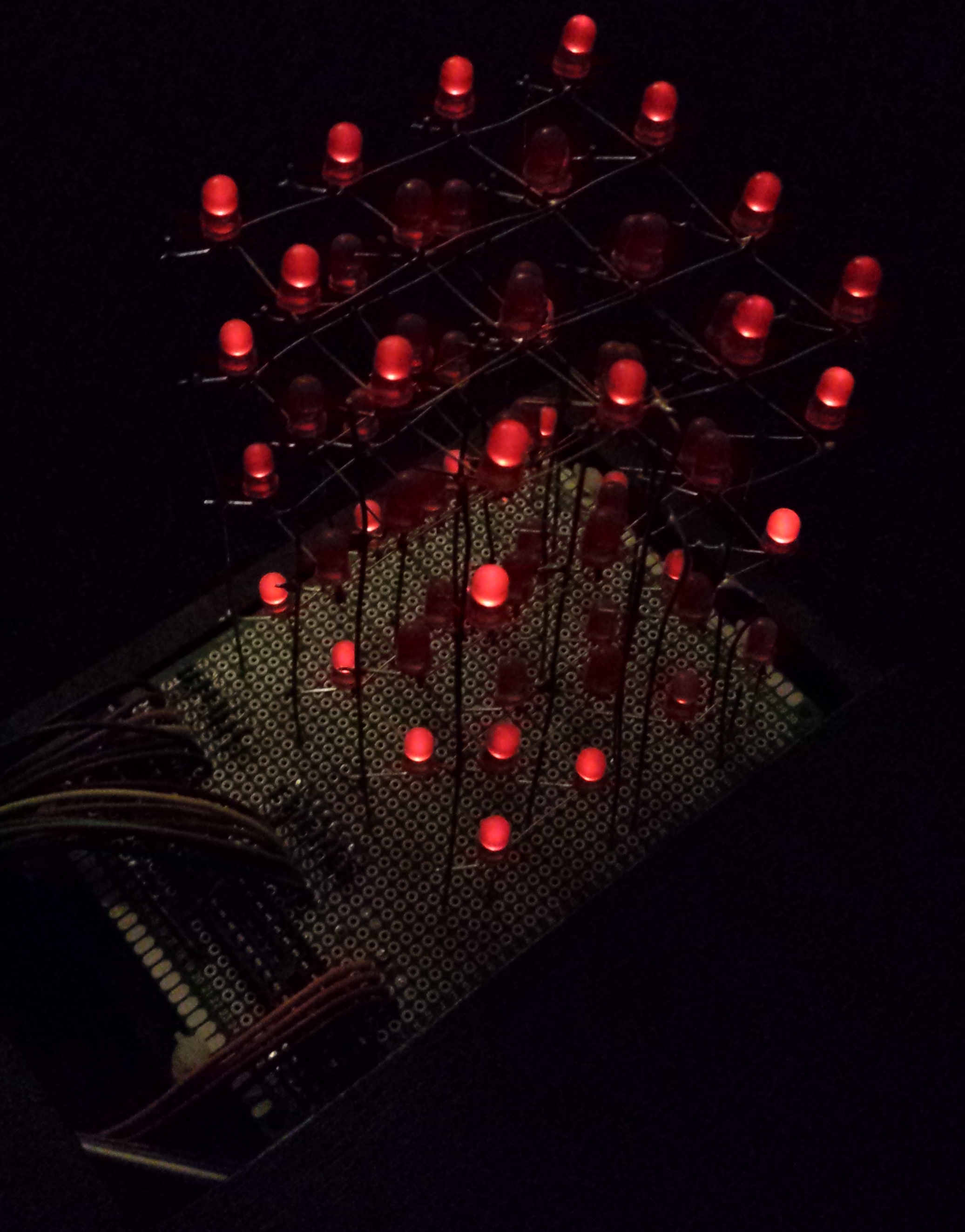
However, I am not an electronic engineer and I had to make some decisions which limited the overall solution. Part of this was the solution was pretty slow and the LEDs were actually not overly bright. The cube looks good in a dark room but you cannot hardly see it in normal lighting conditions.
I was also a bit disappointed in exactly how my cube wasn’t completely symmetrical. Not bad for an amateur but I was hoping for better. This time I was going to try my hand at building someone else’s kit.
Building the cube
The most challenging part is to actually build a LED cube. Keeping the spacing consistent and soldering internal connections of each plane makes building the cube an intricate 3D puzzle.
The plan to create a very symmetrical cube was to build a template to assist in building the layers. The idea is that if each layer is built identically the chances are better that all the LEDS will line up for the rows and columns.
There are two different directions to go, either to build each horizontal layer or to build a vertical layer. In my previous cube I learned the hard way that it is really pretty difficult to assemble these horizontal levels. This was while trying to make 4 internal connections that were not accessible from the edge. Building a larger cube will have considerably more internal connections, in the case of a 8x8x8 cube this would be 49.
My mentor Mikhail suggested that it would be much easier if I used a vertical slices. He suggested it might make the assembly easier. I have seen other examples on youtube assembling either as slices or even just adding each column as it is completed.
First attempt
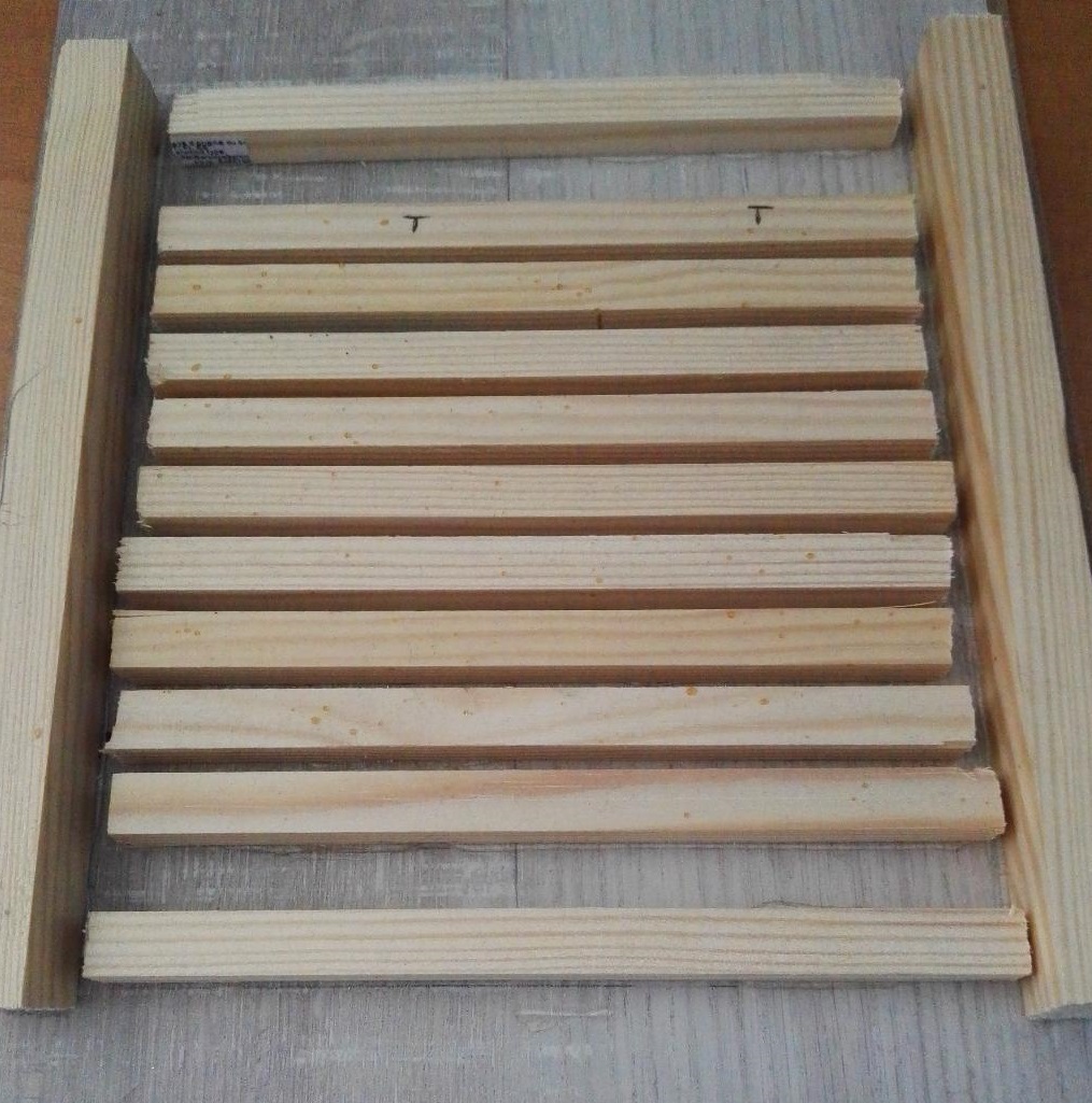
The first step was to try and build the template to create each vertical slice.
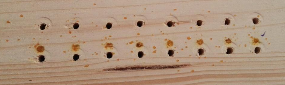
 The template looks pretty good in this picture but unfortunately looks can be deceiving. The actual LED’s are not perfectly aligned but more importantly the groves are not all straight, some of them angle slightly. This makes it quite difficult when trying to get the layer off of the template.
I tried to create a few small “slices” using this template but discovered that the defects, mainly the groves for the vertical lines, make using this template infeasible.
Second Attempt
I still wanted to build the cube in slices but I needed some assistance to create a more perfect template. This would be easier if I had better wood working tools and wood working skills so I thought perhaps I could purchase some parts that could allow me to create a consistent template.
I started with small wooden blocks that already had a hole drilled through them. Despite how similar they appear in your hand they are not truly identical. My solution was to get a long straight wire to help ensure that they are all nicely aligned. It is not obvious but after all the blocks were glued down I had to add glue around each block to help make each block more secure.
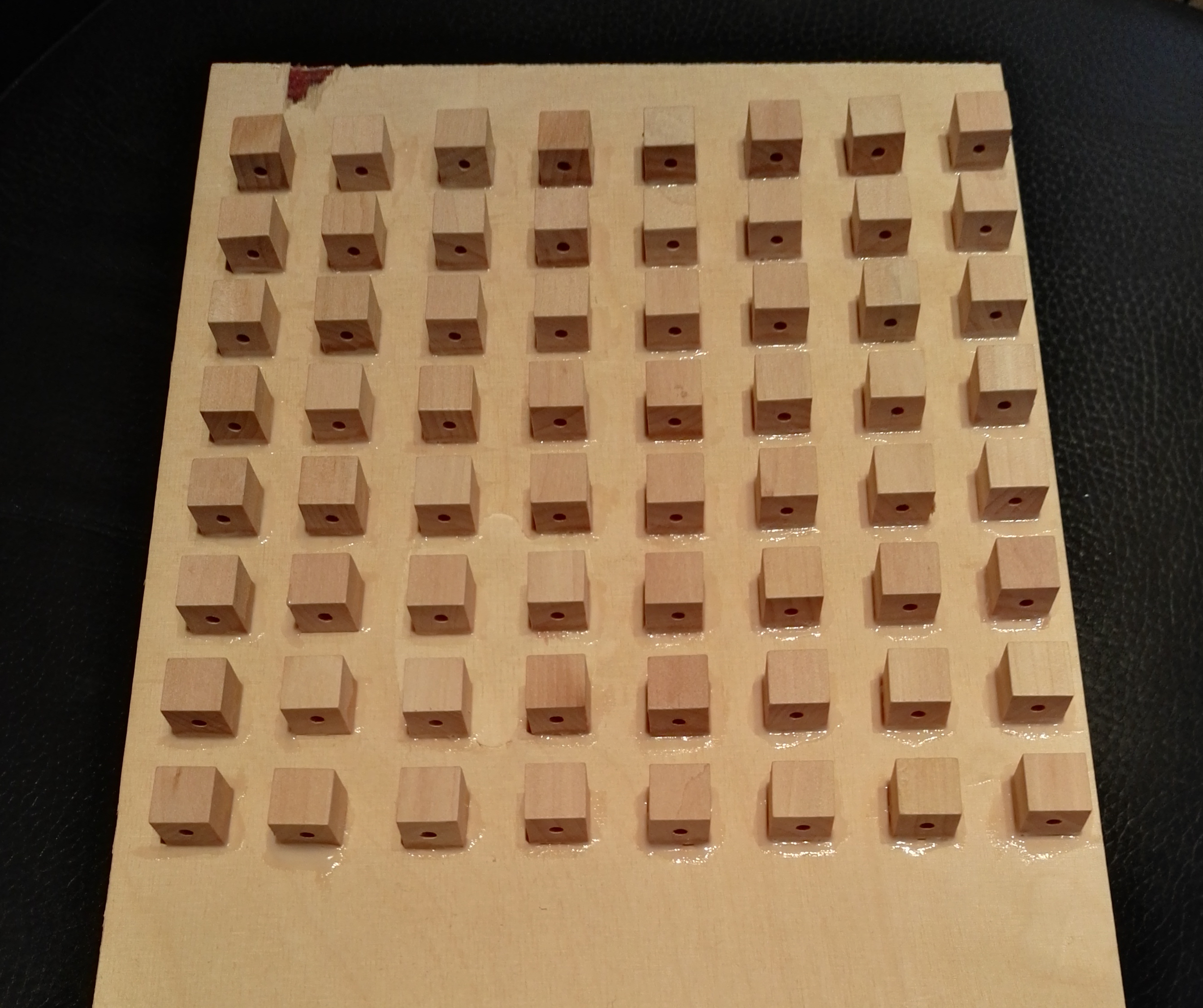
This template for building a panel does not use the legs of the LED’s hardly at all.
Third Attempt
My third and final attempt was to to build the cube in an entirely different way.
Of course once you create a lot of rows like this, you need another template in order to assemble them into a panel.
In retrospect this should be intuitively easier to assemble a cube from panels. The problem with building and assembling each layer is that it is necessary to connect up all of the “columns” with a led. In the case of a 8x8x8 cube this is the task of attaching 64 columns on each layer. The wires for each column would of course be standing straight up which means you need to carefully get your soldering iron to each spot without really bending these wires.
Most of the complexity This problem goes away when assembling the cube as a series of side panels. Of course you still do need to connect the different panels together. This task is much simpler as it is no longer necessary to have eight wires connecting each panel together at each layer. One wire is enough. This reduces the number of wires that need to be added to hold everything together from 64 to 8. I actually used a few more than that to give the cube some extra stability.
Another twist
I did play around with this alternative method as well. During my research I saw another cube developer who created a small loop at the end of each leg and then fed the row or column wire through this loop and then soldered it.
This other maker was creating a much more complicated RGB cube and needed to use this method, but it was really convenient in my case as it allowed me to create a very simple cube with clean lines.
In the end, I used both this small loop along with my third attempt at building a template form.
Wire preparation
The template itself actually does quite a bit of the work, it keeps the LED’s separated and at the proper distance from each other. The only tricky part is that you need straight wire for the rows and columns but the wire tends to be purchased in spools.
How to straighten wire was described in how I built my first cube so I won’t elaborate on it much here. I will however give some links to all three methods for doing this.
- Pull the wire slightly [1]
- Use a drill through a board [2] or with a vice [3]
- Straighten between a couple of boards or [4]
- A pair of pliers
In theory any of these methods will work to a certain degree. I never did try the drill method but in the end I decided for the final method. If the wire that you are using for the structure of the cube is reasonably thin it is possible to simply pull the wire a small bit with a pair of pliers just using your hands. You cannot straighten wires that are very long but with this method I could straighten a piece that would later be cut into three smaller ones that are each long enough for a 8x8x8 cube.
I did cheat a bit as I used a vice grip pliers and a pair of pliers.
Other preparation
Actually there is not a lot of other preparation but it is a good idea to test your LED’s before assembly. This step is more important if you are building a cube from scratch because you will most likely have a lot of LED’s available. This step is important if you have a kit yet if one of the LED’s is substantially dimmer or doesn’t work you might find it difficult to get a replacement.
3D LightSquared DIY Kit 8x8x8 3mm LED Cube
I looked at a couple of sources for LED cubes on the internet. I could have purchased one on amazon but they were a bit more expensive than I was willing to spend for testing out someone else’s cube.
I found an 8x8x8 cube kit on Ebay for a very attractive price, so I gave it a try. I was a bit unhappy to see that I received a kit but no actual instructions were delivered. I went to the internet to see if I could find anything that would help me.
I did find plenty of pictures in the google search engine looking for my kit but perhaps one of the most helpful things was the following video and instructions that I found at the instructables.com site
I also saw some good photos from the hackaday.io site. You do have to be careful when putting in some parts such as the resister network and make sure that the capacitors are put with the correct polarity.
Actually putting the board together is really very simple with one little exception. The kit contains a whole set of “round pin needles” which you remove the insulation from and solder into the board. It is really a very clever way of connecting the LED panels to the board but it is an entirely irritating way thing to actually solder. No matter how I tried to solder these it it seemed that when I rotated the board that I soldered them in at a slight angle in one direction or another.
In the end this wasn’t quite the problem that I had initially thought as I choose a completely different method of building my panels.
The manner that the panels were built at the instructables side was using the legs of the LEDS as the wire for all of the columns and rows. That actually should help most beginners, including myself, a way of consistently connecting everything up. I would have considered doing this earlier but I didn’t like the method of connecting the panels.
If you look closely at the pictures from the instructables site you will notice that the LED’s in that example was pointing to the side instead of the more normal orientation(in my opinion) of straight up. It appears that the orientation on the hackaday site is with the orientation straight up, but the actual cube does not appear to have perfectly straight lines.
The final result is actually very stunning.
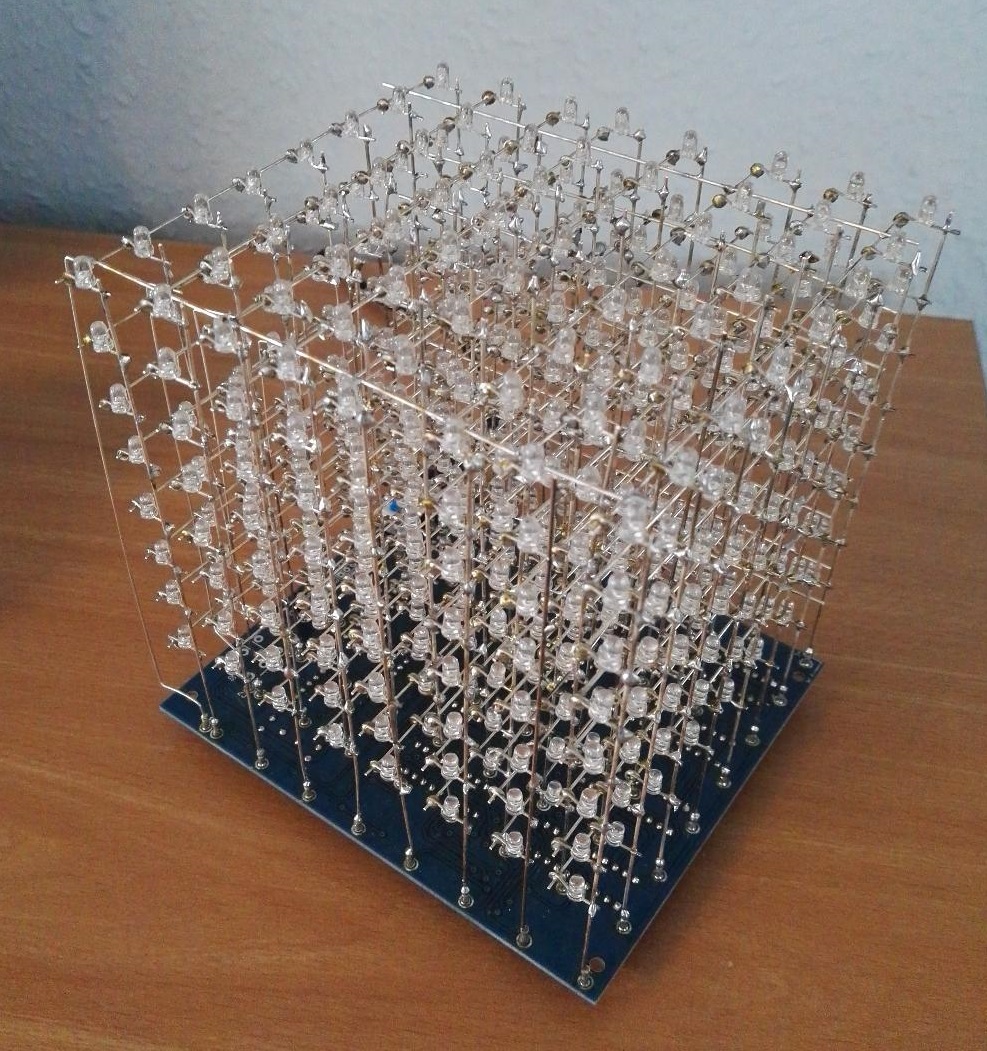
I will upload a video in the near future showing the various patterns of this cube. If I were reviewing this cube I would be stating how unhappy about the lack of instructions but quite pleased with the final results.

![[1]](http://images.google.de/imgres?imgurl=http://pad2.whstatic.com/images/thumb/f/f4/Straight-blocks.jpg/728px-Straight-blocks.jpg&imgrefurl=http://www.wikihow.com/Bend-Wire&h=396&w=728&tbnid=2cdQ-ZsH62r4UM:&vet=1&tbnh=90&tbnw=165&docid=R9w0LOeVxCRRQM&usg=__2cxBUNCTqS3PrZ-LVz-R7HNsJVQ=&sa=X&ved=0ahUKEwiZ2cbnr63RAhUDOsAKHdgqDTMQ9QEIOjAH)