
Some time back, I had a fair amount lot of free time. I spent the time working with a friend Mikhail in the evenings to create my own LED cube from scratch. It was actually quite a bit of fun, the electronics was not overly complicated with most of it being done by a Raspberry Pi. It was fun to see both the hardware and the software side by side.
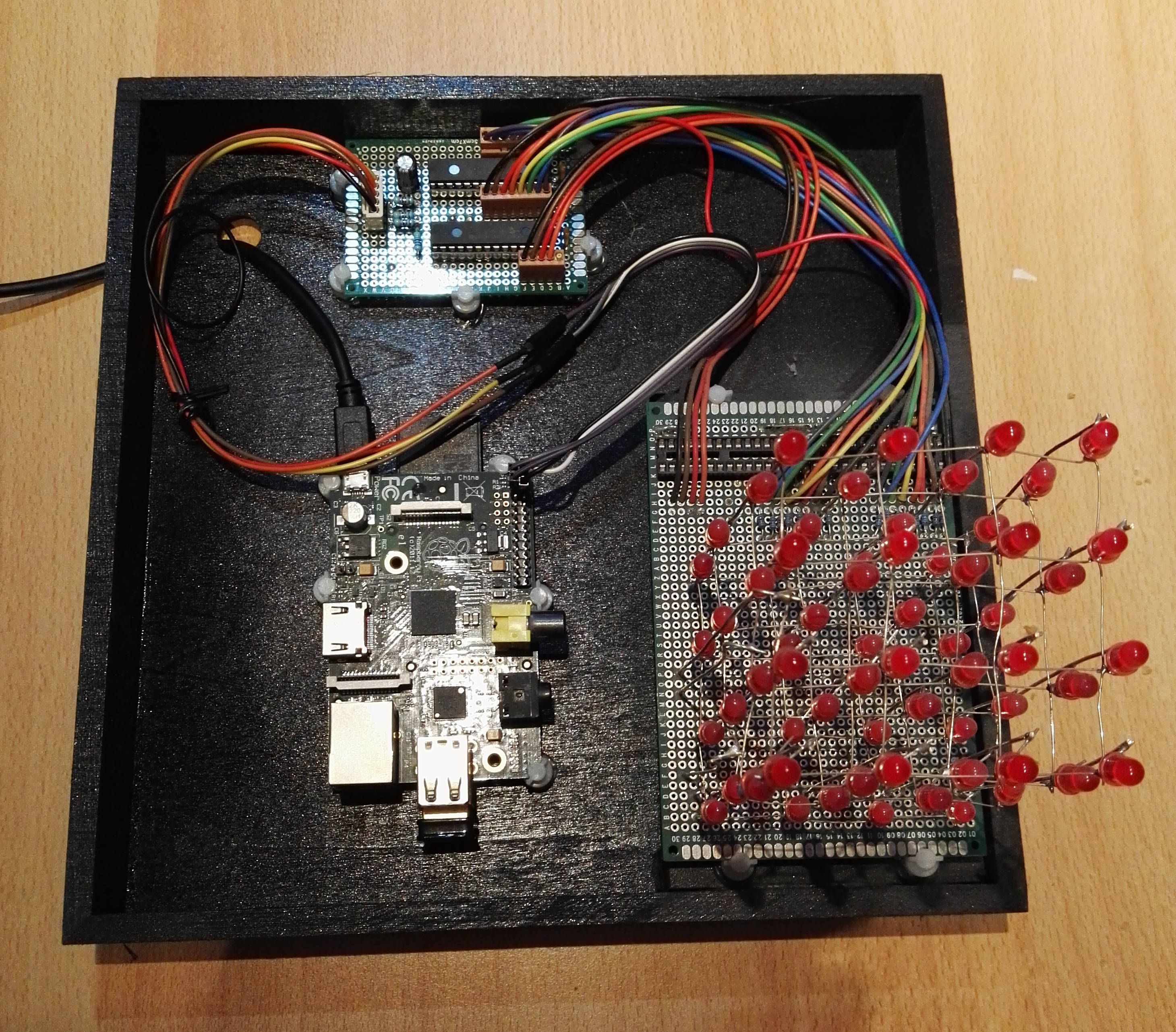
raspberry pi powered cube
The problem with that particular cube was using the Raspberry pi. The Raspberry pi is a great platform but it is a computer and it needs time to start up the operating system and more importantly it needs to be shutdown in an organized manner.
The Raspberry pi is an awesome little computer but the startup and shutdown times are my main problem. I only have a few hundred lines of code that needs to be run so I don’t need a four core 1.2 gHz computer, only need a few megaherz.
Arduino to the rescue
The first release of the Raspberry pi was in 2008 at 900 mHz for 35 dollars was truly amazing but it wasn’t the first of this type of hardware for do-it-yourself electronic projects.
I actually was never involved in the DIY electronics when the Arduino came out but I think that the Arduino was pretty much the pioneer of this space. The Arduino was not only hardware but it was open source hardware. The fact that it was open source helped it to expand and multiply into the number of models that we see today. Well, being open sourced helped but also due to the release of ever increasing sophisticated processors from ATMEL which powered these Arduinos.
Today it is possible to get what is essentially little computer that is not much larger than a couple of postage stamps.
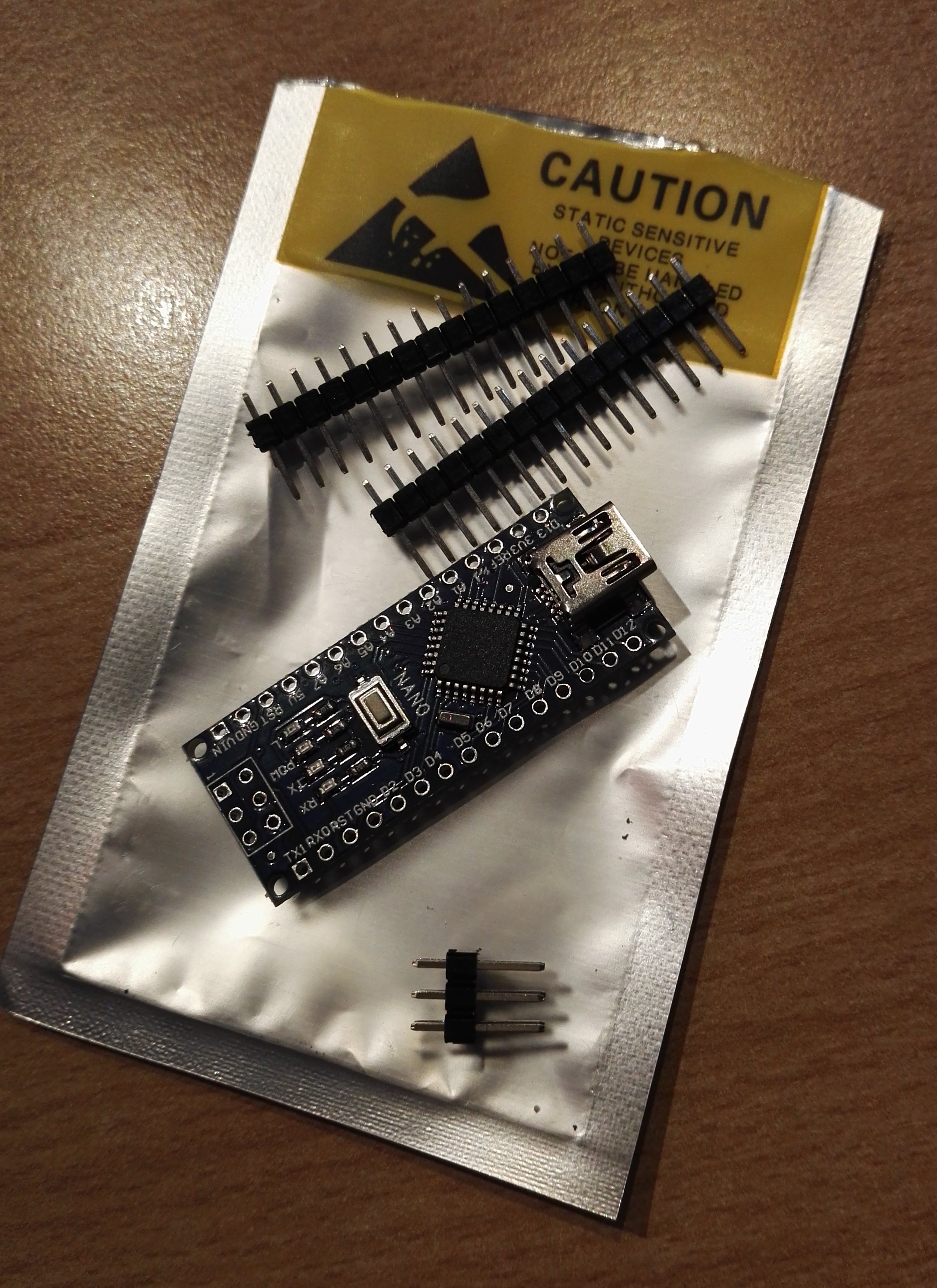
This “advanced” processor is running 20 MHz and contains 32 KB of program memory. Not quite the latest gaming personal computer but it is similar to the original Apple ][ personal computer, but it is more than enough to pass the commands to the cube to switch leds on and off using the I2C protocol.
New Hardware
The Raspberry Pi supports I2C but the Atmega328 does as well. The I2C protocol is just a matter of two lines – a data line and a clock line. As far as the hardware was concerned, all I needed to do was to connect the data, clock, power and ground to the Arduino atmega328.
On the software side, I was pleasantly surprised at actually how easy it was using the Arduino libraries to do I2C and to convert my code over.
Sure, I did have to make a number of small changes but the process was pretty painless. Replace my printf statements with Serial.println statements but the main changes were connected with the I2C protocol.
The libraries to do this were part of the standard development environment. The class that you need to use is the Wire class.
Old Code
   bcm2835_i2c_setSlaveAddress(cathode);
   char cmd2[] = { IODIRA, 0x00, 0x00 };
   check_retcode(bcm2835_i2c_write(cmd2,sizeof(cmd2)));
New code
   char cmd2[] = { IODIRA, 0x00, 0x00 };
   pi_i2c_write_command(cathode, cmd2, sizeof(cmd2));
The pi_i2c_write_command is my own method but it simply does call the three methods (beginTransmission, write, endTransMision) that are required in order to send an I2C command. Only five lines of the twenty six are required, the rest were used for monitoring the program while it was being ported.
void pi_i2c_write_command(int device_address, char cmd[], char len)
{
  int idx = 0;
  if (debug != 0)
  {
    Serial.println("begin pi_i2c_write_command\n");
    Serial.print("address ");
    Serial.println(device_address, HEX);
    Serial.print("arguments ");
    Serial.println(len, DEC);
    for (idx = 0; idx < len; idx++)
    {
      Serial.print(cmd[idx], DEC);
      Serial.print(" ");
    }
    Serial.println("\n");
  }

  Wire.beginTransmission(device_address);
  for (idx = 0; idx < len; idx++)
    Wire.write(cmd[idx]);
  Wire.endTransmission();

  if (debug != 0)
    Serial.println("end pi_i2c_write_command\n");
}
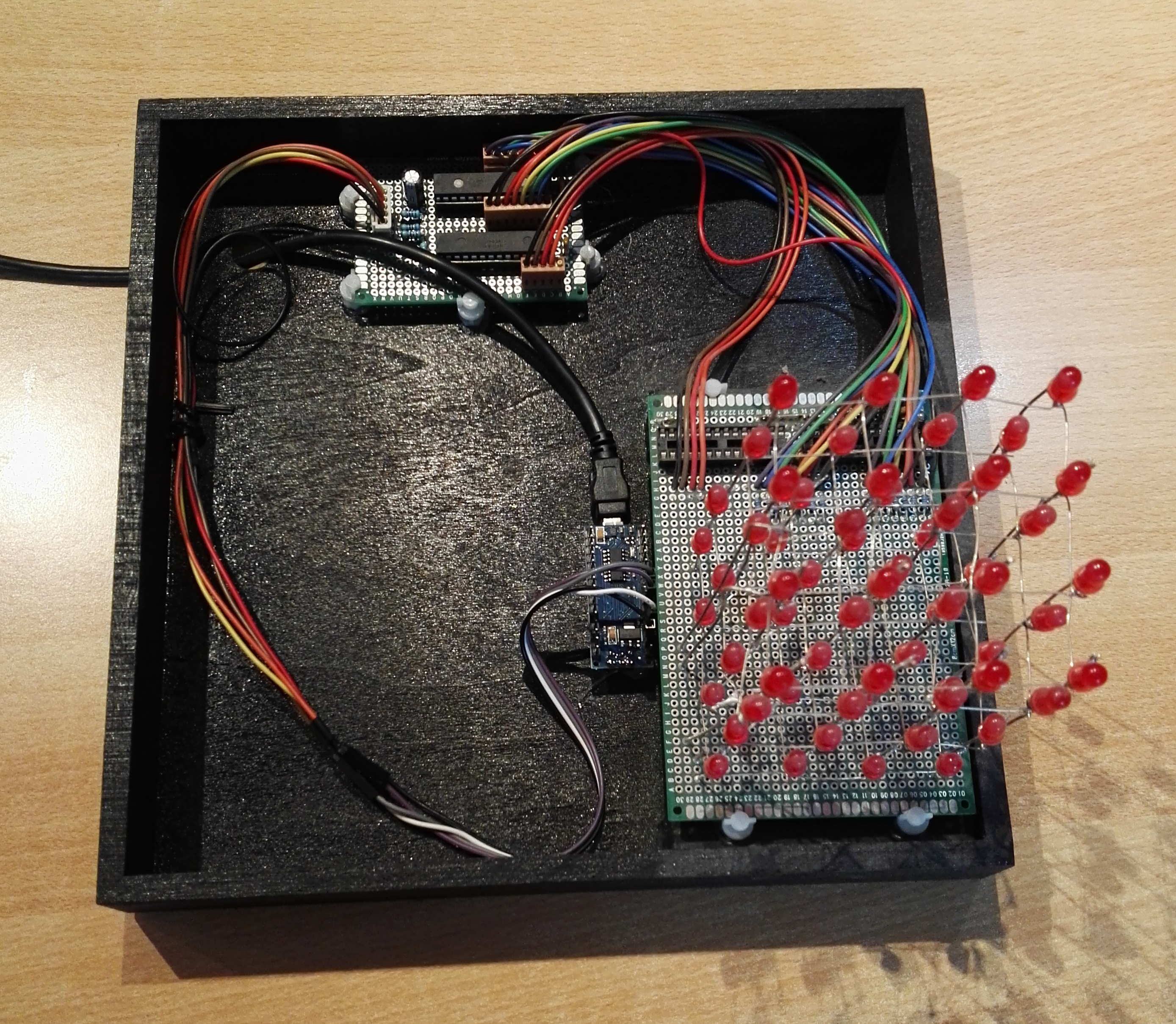
arduino powered cube
The Problems
I did have one small problem while porting my software that was really an oversight. Before you try and transmit any data via the I2C bus you need to initialize it first with the a call to “begin”.
Wire.begin();
If you don’t make this call, none of the subsequent calls do anything. In my haste, I did have this line but it was in the wrong spot in my initialization code.
My code does have comments but it has been a while since I was using the 23017 16 bit I/O expander. So I did have a few questions how it worked exactly.
While doing my debugging I did read up more about the chip and I do have a few clarifications that describe the code’s behavior.
| register | Description |
|---|---|
| IOCON | This register is used to set various configuration options on the chip. The two most interesting as far as this program goes is the BANK (bit 7) and the SEQOP option (bit 5).
The BANK bit changes the addresses of the various registers. When BANK=1 then the address for IODIRB is 0x01 but when the BANK=0 then the address for IODIRB is 0x10. The order of the registers is more interesting in conjunction with the SEQOP register. The SEQOP=1 allows the chip to write multiple bytes sequentially. When the BANK=0 then the register pairs are next to each other. |
| IODIRA
IODIRB |
These registers are used to set the direction of the I/O. The IODIRA register controls the direction for first 8bit port (PORTA) and the IODIRB register controls the direction forthe second 8bit pot (PORTB). |
| OLATA
OLATB |
These registers are used to set or clear the latches for the two ports. |
The other important detail is that the current flows to the various LED’s (via the I/O expander) when the anode (layer) is set to on and the cathode (column) is set to off. This sounds exactly what you would expect for lighting up a LED, power goes to anode and ground goes to cathode.