
Some time back, I had a fair amount lot of free time and did watch things on you tube. A friend of mine showed a number of cool LED cubes that were trending at that time.
It seemed so cool and considering our combined backgrounds a natural that we should try and create our own control board for our own LED cube. He was the hardware engineer so I left him to that task while I thought about patterns and programming the cube.
Yet, despite not being the hardware type I thought I could create my own, albeit less sophisticated cube, with only a small bit of effort.
Come on just how hard could it really be?
Bring in the pie’s
Part of the reason I thought this would be so simple is that I was also playing around with the “Raspberry Pi”. The specifications for the pi were not all that impressive when compared to my laptop but it was a truly amazingly affordable and small computer that also offered a comfortable Linux distribution for running it.
The Raspberry Pi that I was using is basically just a small computer with the power of a smart phone from 6 years ago.
- ARM11 700 mhz
- SoC is a Broadcom BCM2835
- 512MB RAM
- 2 USB ports
- Ethernet port
- 3.5mm jack for audio out
- HDMI
The operating system is a derivative of Debian. Communicating with the Raspberry Pi can be done just like any other computer over the Ethernet or perhaps by using a WiFi dongle.
Communication between the Raspberry Pi and other external peripherals is done via the general purpose I/O pins. The GPIO is the break out of the functionality in the Broadcom BCM2835 system on a chip which in additional to other functionality also includes the support for I2C and SPI as well as UHF transmission.
I2C and SPI are two different but common communication bus protocols for communication between micro-controllers and other components or peripherals. The protocol allows a component to send commands to a receiving component. This is a really convenient way to delegate tasks to other devices, but inter-device communication is not the only advantage of the GPIO.
The other advantage of the GPIO pins is that it is possible to use it to turn on or off something connected to one of these pins. This can be used to enable or disable other devices or even simple things like turning on a motor or a LED.
How LED cubes work
LED cubes create neat images by turning on LED’s in rapid succession in order to creates letters or patterns. The power required to turn on all the lights becomes more and more considerable as the cubes get larger and larger. A 3x3x3 cube can easily be powered by a 9 volt battery but a 8x8x8 or 16x16x16 cube would require a an actual power supply.
The thing that is the same no matter of the size is that the cubes only turn on a single led at a time and rely on persistence of vision to fool the eye into believing that all the LED’s in the pattern are on at the same time.
Persistence of vision principle is essentially the same concept underpinning “moving pictures” aka cartoons. The eye cannot distinguish between changes that occur too quickly and so it will see it as a single picture. Thus when the different LED’s in a cube switch rapidly on and off the eye simply sees the LED’s were on.
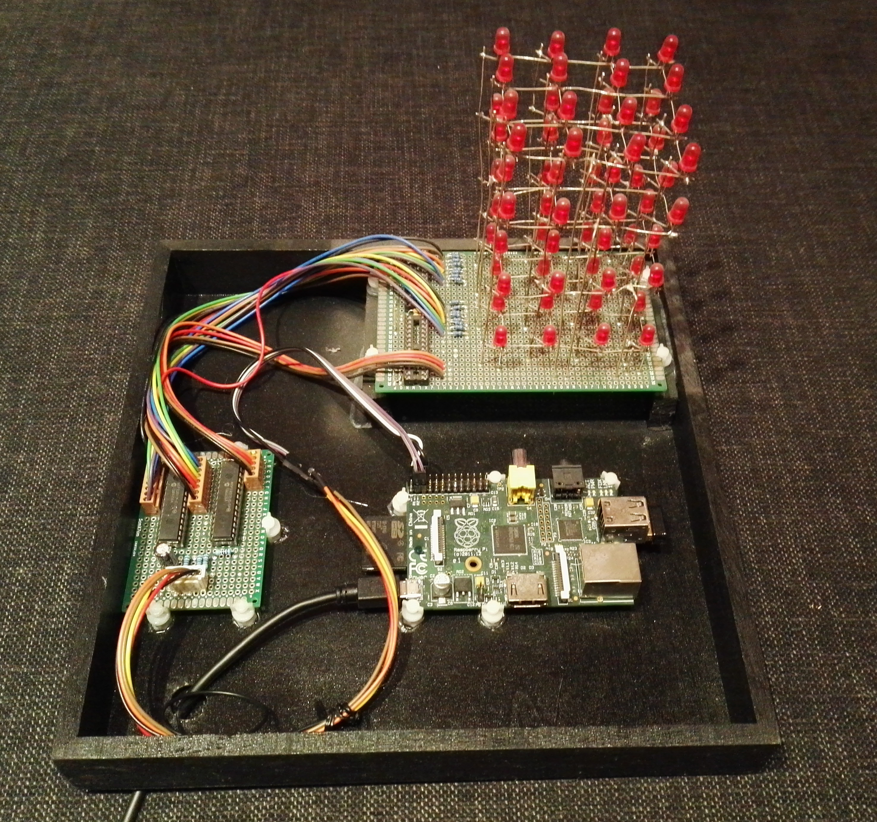
My own cubes logic
The first thing that I needed to be consider was how to power each led. Four levels of 16 LED’s gives a total of 64 LED’s or 128 legs (anode and cathode) for the cube. The total number of GPIO pins available on my Raspberry Pi is 26. Even if I could use every single one of these pins this would be nowhere near enough pins for this small project.
This is a very important point as not every one of these pins is even available to be used. Some of these pins are used for I2C or power or ground which leaves me severely lacking if the goal is that the Raspberry Pi is to drive everything directly.
Yet, I cannot be the only person or manufacturer to have encountered this problem and indeed I was not.
23017 IO Extender
The 23017 IO extender has 16 data legs which can be turned on or off. One of these chips alone won’t be enough to deal with 128 legs but there are some clever simplifications to the overall design that will allows me to use two of these chips to drive the rest of the cube.
Because we only need to turn on one led at a time, I can use the IO extender for each of the LED columns. Thus if I provide power for each level, as needed, and allow the current to flow through the led controlled by each column then I can turn on or off any led at any spot on the cube.
This means that I will need to use one of the 23017’s only to control the columns but then I need a way to control which levels get the power. This is done by using a second 23017 to control which level will receive the power.
How this works is as follows. A light bulb or a LED cannot light unless it receives a path to power and ground. When this happens the electricity flows through lighting up the element. Controlling a light bulb is done using a normal wall switch, and this can be done for a LED as well. However, for a LED in a circuit another possibility is to prevent the power from flowing.
This is done if either no current is provided for the input (anode) of the LED or no ground (cathode) provided to complete the circuit. If both of these pins are set to ground or both are provided voltage the current will not flow and the LED will not light up.
This how my cube controls the individual LED’s. Once the program decides which LED to light up, it will provide current to that level and will set the cathode for that LED to ground.
Well, this is how my circuit behaves, but the Raspberry Pi is not toggling the state of the LED’s directly but actually using I2C to send a command to both of my 23017’s to enable each LED. Each 23017 is given a different address so it can be controlled directly. This is done by setting the pins 15 – 17 to a unique value for the 23017 chips that you are using.
MCP 23017
| Pin | Name | Description |
|---|---|---|
| 1 | GPB0 | I/O port B |
| 2 | GPB1 | I/O port B |
| 3 | GPB2 | I/O port B |
| 4 | GPB3 | I/O port B |
| 5 | GPB4 | I/O port B |
| 6 | GPB5 | I/O port B |
| 7 | GPB6 | I/O port B |
| 8 | GPB7 | I/O port B |
| 9 | VDD | 5 volt power |
| 10 | VSS | ground |
| 11 | NC | unused |
| 12 | SCL | Clock pin |
| 13 | SDA | Data pin |
| 14 | NC | unused |
| 15 | A0 | Address |
| 16 | A1 | Address |
| 17 | A2 | Address |
| 18 | Reset | Reset |
| 19 | INTB | Interrupt B |
| 20 | INTA | Interrupt A |
| 21 | GPA0 | I/O port A |
| 22 | GPA1 | I/O port A |
| 23 | GPA2 | I/O port A |
| 24 | GPA3 | I/O port A |
| 25 | GPA4 | I/O port A |
| 26 | GPA5 | I/O port A |
| 27 | GPA6 | I/O port A |
| 28 | GPA7 | I/O port A |
This table is intended to give a brief overview. To have a full understanding you will need to reference the specification sheet for this chip.
Reading through the I2C specification of how exactly the bus functions is fascinating but perhaps a small it intimidating at the same time. The nice thing for the application developer is that, more likely than not, this is a low level function that you call with some parameters.
In my case I was able to find a open source library on the internet which supported the BMC2835 chip which included an I2C support.
Circuit diagram
Despite how complex this circuit may appear it is simply two IO extender chips, three capacitors and twenty resisters.
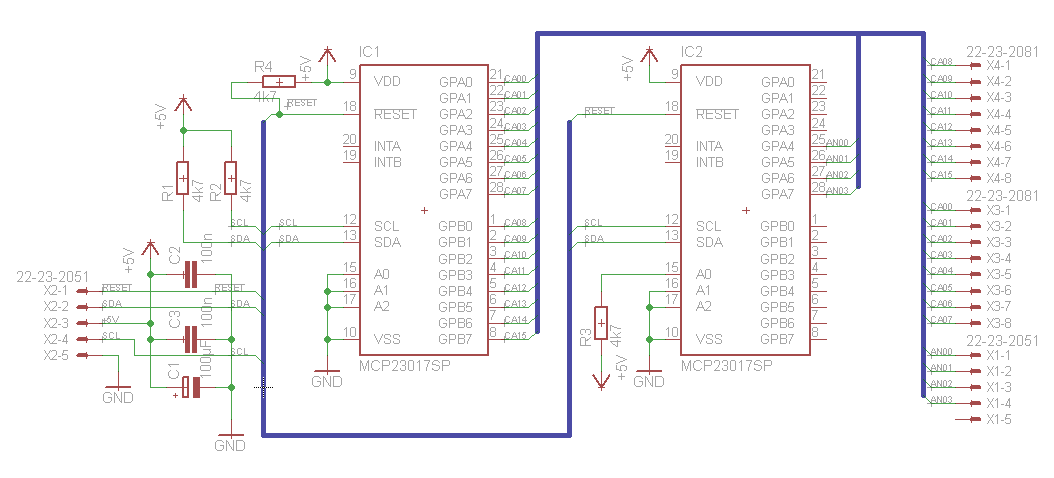
Somewhat contrary to what you might think, the circuit diagram wasn’t created so we could create the following board.
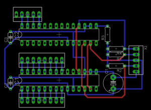
We created the board layout in order to design an optimal layout for the individual connections.
There is really very little needs to be described for this circuit. On the left side of the circuit is a simple five line connector connector. These lines will connect to the Raspberry Pi which will provide power, ground and the SCL and SDA in order to use I2C to communicate with the 23017 chips.
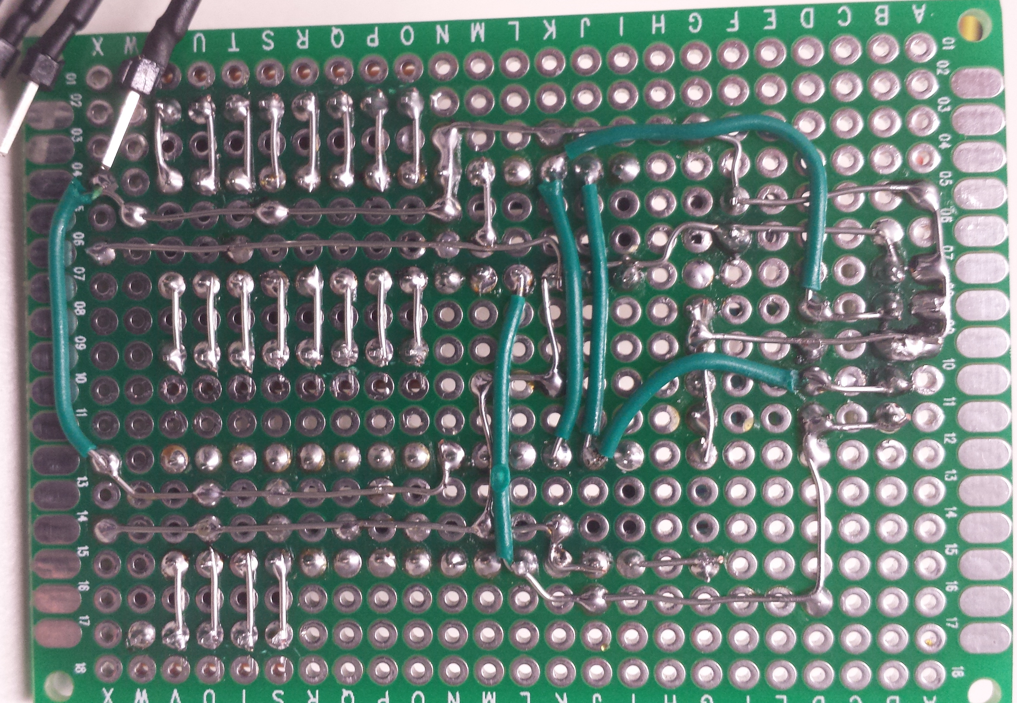
Building the cube
Building the actual LED cube is both the easiest and the hardest part of this project.
layers
On one hand it should not be overly difficult to solder together the LED’s. It is just a matter of soldering each LED to a wire. This should be made even easier by creating a template to hold all of the LED’s still in the proper relative positions to each other.
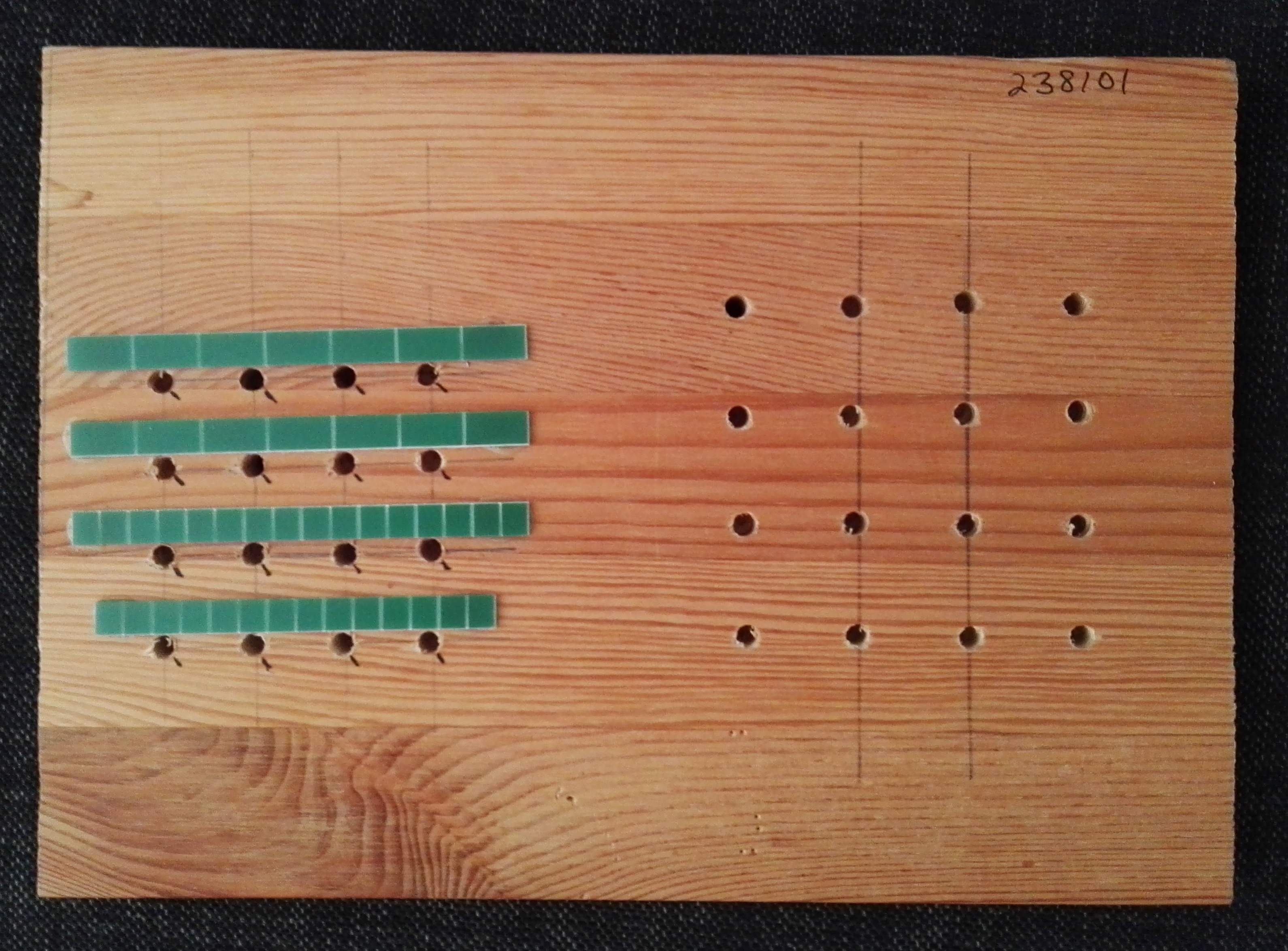
Indeed this template makes it relatively easy to create a plane of LED’s. You can take as much time as you need and there is no need of any additional tools or assistants to make these planes. One minor inconvenience is to find your own way to create straight wires.
If the wires are not straight then the rows or columns won’t be either. While preparing for this I have hit upon three different manners to prepare the wires.
- pull the wires
- use a drill
- use a couple of boards
The first two methods pretty much require a vice. Simply connect the wire to the vice and either pull the wire ever so slightly or put the other end into a drill and briefly run the drill. Both of these methods actually stretch the wire slightly which is what causes it to straighten out.
I only saw a single video on the topic of using boards to straighten wires, and somehow I lost that link. The idea is pretty simple, you need a flat board and a small thin board that is at least as long as the wire and approximately six cm wide.
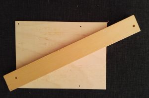
Just place the wire on the flat board and set the smaller board on top of it. Rub the wire left and right as many times as it takes for it to straighten out. This is a very convenient method as long as the wires don’t need to be too long.
Assemble the layers
The most challenging part is the assembly of the different layers. I don’t think using the word trivial is correct for creating the layers but you can work and re-work them until you are happy. The hard task is the assembly.
The reason this is so difficult is that this method of assembly requires that you use your soldering iron for each layer and you need to solder in the middle. This is fairly easy for the first one but gets more complex as more layers are added.
In addition, you have to be extremely careful not to accidentally touch any of the wires with your soldering iron otherwise too much heat may be transmitted to the nearest solder joint. If the LED’s or wires have any pressure pushing them apart this heat may be all it takes to cause a previously soldered part to either come loose or become a weak joint / loose connection. It is very difficult to re-solder these connections once the cube is built. This would become even more problematic the larger the cube is.
The level of difficulty assembling in this manner due in part to how densely packed the cube should be. This is both the horizontal and the vertical density. Two difficulties present themselves.
The first difficulty is how much spacing to keep between each plane. The second and related problem is ensuring that the spacing is kept uniformly for each layer and for all subsequent layers.
I didn’t do it with my cube, I used wires for most of the structure, but quite a few other cubes are built using the actual cathodes and anodes to build up the cube structure. If this were done it would help considerably with the spacing problems.
Drawbacks of this design
My father always said that you should use the correct tool for the job. In this case, I imagine that the right tool would have been an electrical engineer.
As long as you already have a Raspberry Pi, my design is a low cost, low component count that can easily be put together either with a breadboard or with a small amount of soldering. Yet, the Raspberry Pi is not a power plant, there are limitations to how much power it can produce.
The power required to turn on all the lights becomes more and more considerable as the cubes get larger . A 3x3x3 cube can easily be powered by a 9 volt battery but a 8x8x8 or 16x16x16 cube would require a an actual power supply.
My solution is using I2C for communication with the LED’s via the 23017. The only problem is that I found this communication to be pretty slow. My LED’s were not as bright as a lot of the other LED cubes that you can see on youtube.
It was because of the power limitations on how much current can be channeled through the MPC23017 that caused me in the end to take a conservative view and cause me to pick the low power LED’s. The good news is that if I turn on every LED in my cube at the same time it is pretty much within the limitations of the power that can be driven by the 23017. The cube looks good in a dark room but you cannot hardly see it in normal lighting conditions.
I was also a bit disappointed in exactly how symmetrical my cube was. Not bad for a first attempt but I was hoping for better. Unfortunately, the actual LED cube is the product of its creator and the result is unrelated to using a kit or creating everything from scratch. The best results are most likely to be attributed to slow and steady work and a great deal of thought and preparation.
In retrospect the biggest flaw in my design was originally its biggest strength. The nice thing about using the Raspberry Pi was I simply used secure shell to connect to the computer and wrote, compiled, and debugged the code in one easy step.
The only problem is that the Raspberry Pi is a computer not some off the shelf device with a micro-controller. This means that when you turn it on, it takes a while before the computer is booted up and the application can start.
The startup isn’t the problem, the problem when it comes down to shutting down the cube. The Raspberry Pi doesn’t doesn’t have an on / off button so to shut it off I need to open up a secure shell to the Raspberry Pi and then issue a shutdown. Once the device is shutdown then unplug the power supply.
Because the Raspberry Pi isn’t really doing anything special it could have been replaced with either an Arduino or a smaller Arduino and my custom controller board.
Alternatives
The internet is full of instructional videos, instructions and photos of how to make your own LED cube.
One of the difficulties that I mentioned was that building a cube from horizontal layers. The next cube that I would make would take a one of two different alternatives. The first is to simply solder together an entire column of LED’s and then start to solder them to the board and to each other. The second alternative is somewhat similar. Simply solder together vertical panels and solder them together.