
I kept telling Mikhail that the big advantage to using the Raspberry Pi was no matter what project I put it into I could set it on the window sill and ssh to it. It was a fast small and affordable personal computer. He kept telling me that the Raspberry Pi and Raspbian wasn’t a real-time solution and that I should consider something else.
He was of course right but this didn’t matter for most of the things that I was using the Raspberry Pi. The best example of a custom solution was the led cube that I created that displayed various patterns.
The Raspberry pi did a super job for my cube but when I tried to use it on a distance sensor project using the HC SR04, I definitely had mixed results.
I wanted to use my cube more often but there was no convenient way to turn it off, well without first connecting to it via ssh and shutting it down. It took too long to boot, too long to shutdown, and requires a proper shutdown. What about migrating from a computer to a micro-controller – it starts faster and can simply be powered off.
Cheap as potato chips
Mikhail kept telling me that micro-controllers were cheap as potato chips and could easily be included into virtually any project. To encourage this path he decided to do this old school which meant a pile of chips, an AVR programmer, LED’s, resistors, a breadboard and a bunch of wires.
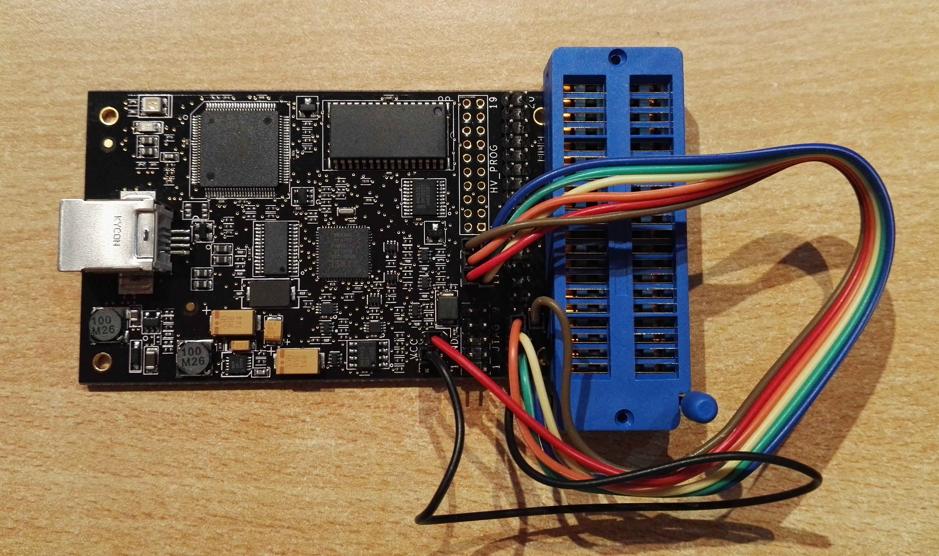
AVR Programmer
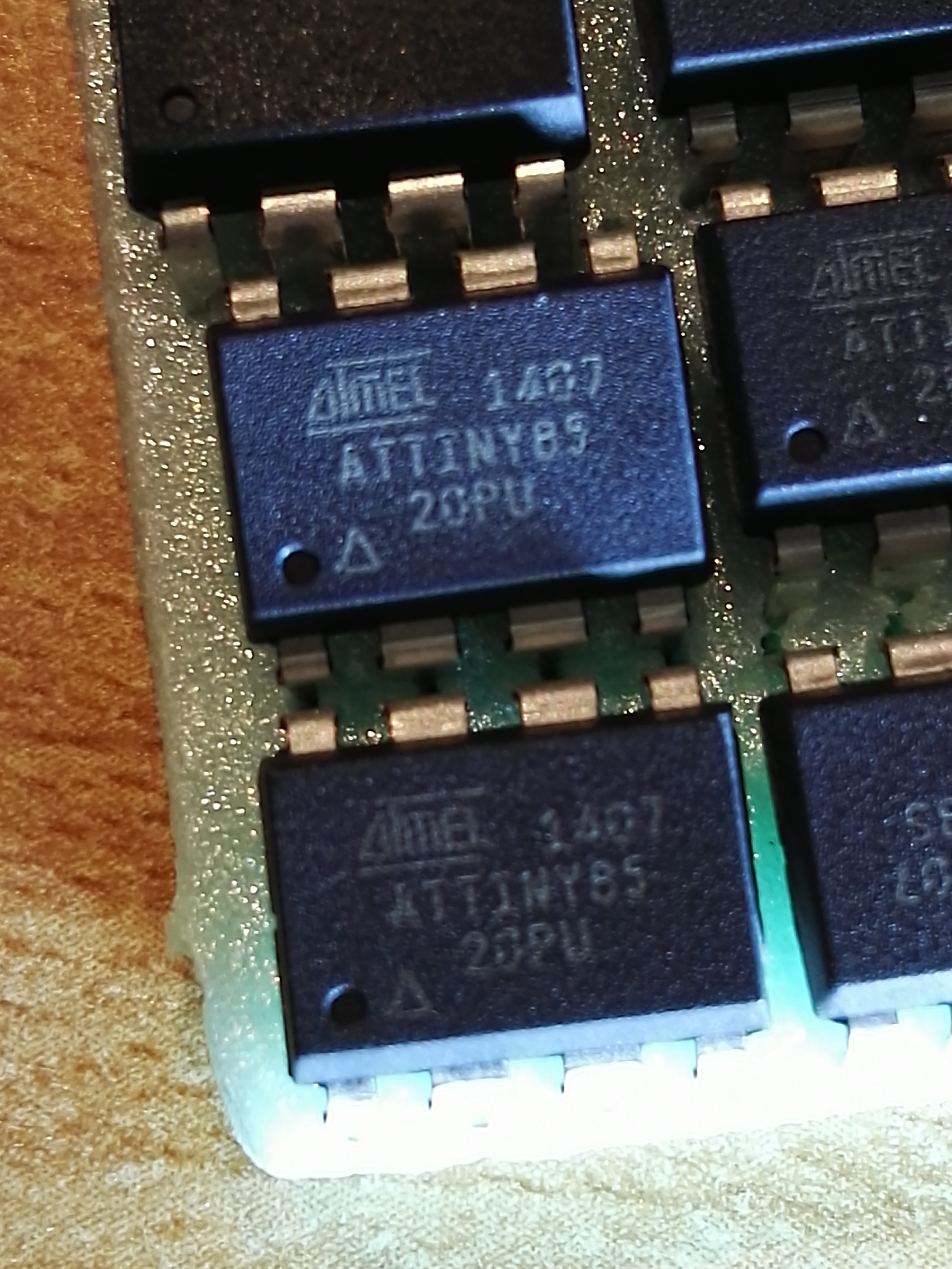
attiny85
Mikhail comes from the electrical engineering side of computers and it was him who discovered, all those years back, some of the interesting projects being done with LED’s. Below are a few interesting projects that he showed me from the internet.
Well, I come from the software side but was willing to learn. I no longer have photos of those old projects but I put together a rather similar example.
Instead of one of those ATTINY85’s I have used an ATMEGA328. Granted the 328 is a much nicer chip but for the task of doing I2C the two chips are equivalent.
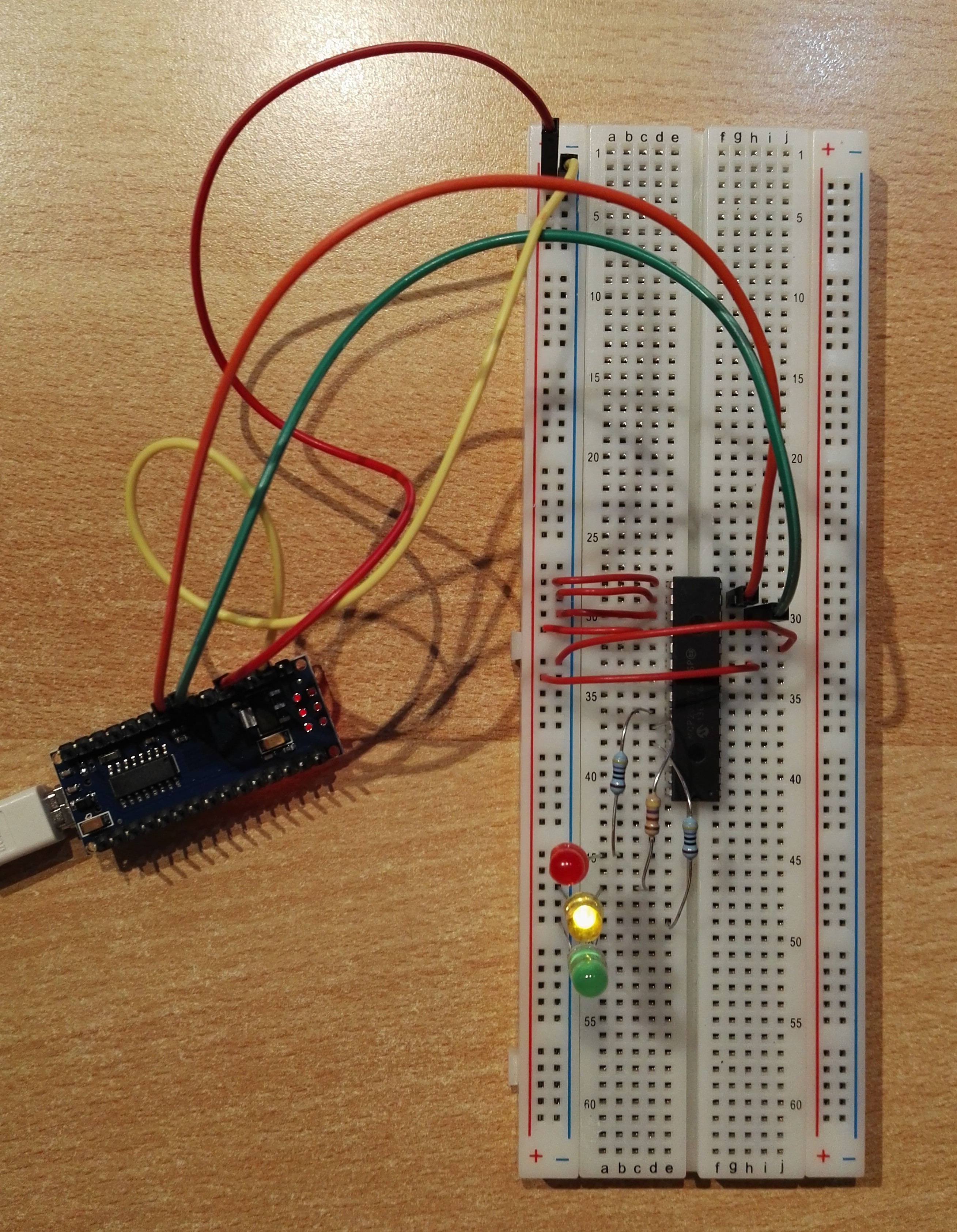
Hardware setup
It has been awhile since I used Fritzing or Eagle to write up a circuit diagram. I will simply show which pins need to be connected up.
| ATMEGA328 | MCP 23017 | Comments |
|---|---|---|
| A4 (pin 24) | Pin 12 | I2C pin SCA |
| A5 (pin 23) | Pin 13 | I2C pin SDA |
| 5V | Pin 9 (Vdd) | 5 V power |
| GND | Pin 10 (vss) | Ground |
| Pin 15 (A0) | tie to ground | |
| Pin 16 (A1) | tie to ground | |
| Pin 17 (A2) | tie to ground | |
| Pin 18 (! reset) | tie to 5v | |
| GPA 4 | connect to led | |
| GPA 5 | connect to led | |
| GPA 6 | connect to led |
I2C explained
The I2C bus was created by Philips in the 1980’s. It was actually a rather clever design decision for connecting CPU’s and peripheral chips together. The use of a single bus is much more efficient in terms of wire used. All chips on the bus do listen for commands that are relevant to them. This is is because each chip has its own address and thus listens for its own address.
It is possible to add any number of bytes via this bus to the receiving chip. The bus is bi-directional, I can send messages to another chip but I can also read back responses from those chips.
The actual description of the how the low level technical details for this two line bus is actually better described elsewhere. One explanation can be found on Wikipedia I2C.
The good news is that you don’t need to know how the bits are sent over the wire to use it. Arduino has a very simple class Wire which makes this task almost trivial.
| Wire Method | Description | Example |
|---|---|---|
| begin() | initializes connect to bus | Wire.begin() |
| beginTransmission(adr); | begin command to send to device “adr” | Wire.beginTransmission(0x20); |
| write(byte2send) | sends a single byte to device from begintransmission | Wire.write(0x00); |
| endTransmission() | builds entire command and transmits it to device. | Wire.endTransmission(); |
Lines 10 – 13 is an actual example of sending the value 0x00 to the register “port” on device 0x20.
Software
This sample bit of code will simply turn on the green led, yellow led and red led in turn with a pause between each one and then it will turn all leds on for 1500 milliseconds. Finally it will turn off all the leds for 1000 milliseconds (one second).
This particular project is not completely interesting in itself but rather as a stepping stone to more interesting devices. I will be replacing my raspberry pi with this Arduino in my next blog.
#include <Wire.h>

int GPA4 = 0x04;
int GPA5 = 0x08;
int GPA6 = 0x10;
int PORTA = 0x12;

void alloff(int port)
{
  Wire.beginTransmission(0x20);
  Wire.write(port);
  Wire.write(0x00); // all pins off
  Wire.endTransmission();
}

void scanner()
{
  Serial.println ("\nI2C scanner. Scanning ...");
  int found = 0;

  for (byte i = 1; i < 120; i++)
  {
    Wire.beginTransmission (i);
    if (Wire.endTransmission () == 0)
    {
      #if 0
      // this is much simpler but takes 2k more of program space.
      char buffer[128];
      sprintf(buffer,"Found address: 0x%02x",i);
      Serial.println(buffer);
      #endif

      Serial.print ("Found address: ");
      Serial.print (" (0x");
      Serial.print (i, HEX);
      Serial.println (")");
      found = 1;
      delay (10);
    }
  }

  if (found)
    Serial.print ("Found device(s).");
  Serial.println();
}  // end of setup

void setup()
{
  // real initialisation stuff
  Serial.begin (115200);
  Wire.begin();

  // do a bit of searching for things.
  scanner();

  // setup our 23017
  Wire.beginTransmission(0x20);
  Wire.write(0x00); // IODIRA register
  Wire.write(0x00); // set all of port A to outputs
  Wire.endTransmission();

/* we dont actually use port b
  Wire.beginTransmission(0x20);
  Wire.write(0x01); // IODIRB register
  Wire.write(0x00); // set all of port B to outputs
  Wire.endTransmission();
*/
  alloff(PORTA);
}

void expanderPinOn(int port, int pin)
{
  Wire.beginTransmission(0x20);
  Wire.write(port);
  Wire.write(pin);
  Wire.endTransmission();
}

void loop()
{
  expanderPinOn(PORTA, GPA6);
  delay(600);
  expanderPinOn(PORTA, GPA5);
  delay(600);
  expanderPinOn(PORTA, GPA4);
  delay(600);
  expanderPinOn(PORTA, GPA4 | GPA5 | GPA6);
  delay(1500);

  // off
  alloff(PORTA);
  delay(1000);
}