command line fun – finding the right jar file

Where did I set down my mobile phone is quickly answered by a quick telephone call or a sms from another phone.  If everything were only that simple.

I receive a bit of code from a buddy at work that showed how to do a special calculation with the vendors software using one of the undocumented classes.  I knew I would need it one day so it was cast into my Download directory waiting for that day.

By the time I actually needed it, my friend had long left the company.  It was literally only 15 lines long including all the necessary class declarations and comments.  The only thing that she didn’t tell me was which jar file(s) I would need in my classpath.

This was a real problem as the vendor has slightly under 700 jar files and only about six of them are intended to be used by the customer.  The good thing about Java is that it is really easy to see which classes are the jar file.  This is easy because the jar file is the same structure as a zip file.  This means we can use unzip or winzip to look at the contents of the library.

> unzip -tv special.jar
Archive: special.jar
    testing: META-INF/                      OK
    META-INF/MANIFEST.MF                    OK
    powerfulclasses/                        OK
    powerfulclasses/myMath.class   OK
    powerfulclasses/bobsCode.class   OK

The best course of action would be to write up a script to list the contents of each jar and do a quick grep to find the class in my example.  If I find the class then I have found the jar, well or you might also find a jar that contains an interface for that class or even a jar that contains a similarly named class.

Despite the name of this post, there is really not so much effort for finding the jars.  The jar files are in a series of subdirectories grouped by different subsystems.  It is however much easier to use the find command to gather up the list of jar files.

find /opt/vendorsoft/support/lib -name "*jar" 

I wish I could have created a single line command to gather up the jars, extract the contents and find the special class but with an eye towards expediency I simply created two small scripts.

The first script just gathers up all jar files using the find command and passes the jar files one at a time to the checkit.sh script.  The find command gathers the jars while the xargs command processes them one at a time.

findit.sh

1
2
3
4
#searchpath=/opt/vendorsoft/support/lib
searchpath=.
searchfor=Gen2CatsCompany
find $searchpath -name "*jar" -print | xargs -L 1 ./checkit.sh $searchfor

Each file is passed to the checkit.sh script.  For this particular example each call can be thought of like this.

checkit.sh $searchfor <file here>

The checkit script is even simpler because it is essentially just doing an unzip and piping the output through grep.  That part could have been done using the “-exec” option for the find command.  The only problem is it would find the class but not the name or path of the jar file.

checkit.sh

1
2
3
4
5
6
7
8
echo $2
unzip -tv $2 | grep $1 &gt;/dev/null 2&gt;&amp;1
if [ $? -eq 0 ]
then
 echo .
 echo found $1 in file $2
 echo .
fi

The requirements are simple – find the jar – and the output is also just as simple.

> ./findit.sh
./one/NCSO.jar
./one/mqTransferGenesis.jar
.
found ExceptionIFGenesis in file ./one/mqTransferGenesis.jar
.
./one/jconn2.jar
./one/jconn3.jar
./one/jdom.jar
./one/jhall.jar
./one/junit-4.4.jar
./one/jython.jar
./one/jythonlib.jar
./one/log4j-1.2.14.jar
./one/ojdbc14.jar
./one/surf.jar
./two/mail.jar
>

I did use this small helper to go through the list of all the vendor jar files. Despite having a relatively slow development environment the answer came back in under a minute.

With the necessary jar files I was able to compile my code sample.

Posted in Command line, programming | Tagged , | Comments Off on command line fun – finding the right jar file

Evolution of LED Lighting – software solution

In my previous blog entry, Evolution of LED Lighting – hardware and tools, I only managed to describe the tools and hardware as well as a first project to test the ability to upload new programs to the device.

Some of the more interesting articles on the internet are about using the ESP8266 and setting it up as a web server.  It is a totally fascinating solution but the reason I don’t want a web browser is that I am planning on having more than one device in my network and I don’t want to bring up a web page for each one when I am controlling them.  I would rather have a separate server, perhaps a home dashboard, which will allow me to control the all devices.

My devices won’t be heart pacemakers and won’t be internet facing so I am going to use the UDP protocol.  If for any reason a message gets lost, then I will simply send it again.  If someone is already sniffing my network packets this is probably the least sensitive information that I have to steal.

The standard Arduino libraries actually have some classes to support WiFi bundled with the IDE. When I did my searching on the internet I found some Arduino examples that were using the WiFi, WiFiClient, and WiFiServer and that led me down the wrong path.

Indeed part of my problem was that the ESP8266 environment also has these classes but either I had forgotten to initialize some object or there are other differences.

One of the additional counter intuitive situations is that to do UDP messages you don’t include the WiFIUdp code, but rather just include the ESP8266WiFi.h file instead.

Once you look at the right kind of example it is actually trivial to connect to your device to the network using WiFi.

ESP8266 device

1
2
3
4
5
6
7
8
9
10
11
12
13
14
15
16
17
18
19
20
21
22
23
24
25
26
27
28
29
30
31
32
33
34
35
36
37
38
39
40
41
42
43
44
45
46
47
48
49
50
51
52
53
54
55
56
57
58
59
60
61
62
63
64
65
66
67
68
69
70
71
72
73
74
75
76
77
78
79
80
81
82
83
84
85
86
87
88
89
90
91
92
93
94
95
96
97
98
99
100
101
102
103
104
105
106
107
108
109
110
111
112
113
114
115
116
117
118
119
120
121
122
123
124
125
126
127
128
129
130
131
132
133
134
135
#include <ESP8266WiFi.h>
#include <WiFiUDP.h>
 
// pins for this device
#define ESP8266_LED1 16 // center
#define ESP8266_LED2 2  // edge
 
// wifi connection variables
const char* ssid = "your-ssid";
const char* password = "your-ssid-password";
boolean wifiConnected = false;
 
/////////////////////
// UDP variables
/////////////////////
WiFiUDP UDP;
boolean udpConnected = false;
char packetBuffer[UDP_TX_PACKET_MAX_SIZE]; // buffer to hold incoming packet,
char ReplyBuffer[UDP_TX_PACKET_MAX_SIZE];  // a string to send back
char ack[] = "acknowledged";               // my default response
 
/////////////////////
// my IoT device info
/////////////////////
boolean debug = false;
unsigned int localPort = 8192;
 
void setup()
{
  // Initialise Serial connection
  Serial.begin(74880);
  Serial.println("begin serial");
 
  // turn off both leds on board
  pinMode(ESP8266_LED1, OUTPUT);
  pinMode(ESP8266_LED2, OUTPUT);
  digitalWrite(ESP8266_LED1, HIGH);
  digitalWrite(ESP8266_LED2, HIGH);
  delay(2000);
 
  // Initialise wifi connection
  wifiConnected = connectWifi();
 
  // do UDP setup if wifi connection exists
  if (wifiConnected)
  {
    udpConnected = connectUDP();
    if (udpConnected)
    {
      // show we are connected
      digitalWrite(ESP8266_LED1, LOW);
    }
  }
}
 
void loop()
{
  // check if the WiFi and UDP connections were successful
  if (wifiConnected)
  {
    if (udpConnected)
    {
      // if there’s data available, read a packet
      int packetSize = UDP.parsePacket();
      if (packetSize)
      {
        IPAddress remoteIP = UDP.remoteIP();
        int remotePort = UDP.remotePort();
 
        Serial.print("\nReceived packet of size ");
        Serial.println(packetSize);
        Serial.print("From ");
        Serial.print(remoteIP);
        Serial.print(", port ");
        Serial.println(remotePort);
 
        // read the packet into packetBufffer
        UDP.read(packetBuffer, sizeof(packetBuffer));
 
        // make a zero terminated character array
        packetBuffer[packetSize] = 0;
        Serial.println("Contents:");
        Serial.println(packetBuffer);
 
        // send a reply, to the IP address and port that sent us the packet we received
        UDP.beginPacket(UDP.remoteIP(), UDP.remotePort());
        UDP.write(ReplyBuffer);
        UDP.endPacket();
      }
      delay(10);
    }
  }
}
 
// connect to UDP – returns true if successful or false if not
boolean connectUDP()
{
  boolean state = false;
 
  if (UDP.begin(localPort) == 1)
  {
    Serial.println("\nUDP Connection successful\nlocal port: ");
    Serial.println(localPort);
    state = true;
  }
  else
  {
    Serial.println("\nUDP Connection failed");
  }
 
  return state;
}
 
// connect to wifi – returns true if successful or false if not
boolean connectWifi()
{
  boolean connected = true;
  int idx = 0;
  WiFi.begin(ssid, password);
  Serial.println("\nConnecting to WiFi");
 
  // Wait for connection, up to 5 seconds
  while (WiFi.status() != WL_CONNECTED)
  {
    delay(500);
    Serial.print(".");
    if (idx > 10)
    {
      connected = false;
      break;
    }
    idx++;
  }
  return connected;
}

This code is great.  It actually allows me to get an IP address from my DHCP server and to start to listen for some UDP messages.

Most of this example code is nothing special.  Of the 135 lines only about about a dozen are required to setup and do all of the networking.

function loop

Lines 64 determines that if a UDP packet exists line 78 reads the packet into our buffer.

Lines 86 – 88 simply send back a response to the machine that sent us the packet.

function connectUDP

The only interesting line is 100.  This is setting up which port that we wish to monitor.

function connectWifi

Lines 119 and 123 perform the connection to our local WiFi network.

It is really a tribute to the people who put together all of supporting code that make these small devices possible.

Testing

The advantage to the web server solution is that at this point you are done.  Simply point your browser at the device and start to click on buttons to control it.  I choose to send UDP packets to my device so now I need a special program on my personal computer that can send commands to the device.

I am not a network programmer so I was happy to see that there are a number of different examples available on the internet.  I will use the Java UDP example on laptop during testing but may ultimately end up using the C UDP example from my home automation server.


Everything at this point looks pretty good.  I have a device that can connect to my network and I have a small client program that can send it messages.  I now have my very own starting point for any generic device that should be controlled via WiFi.


Posted in programming, Setup From Scratch | Tagged , , | Comments Off on Evolution of LED Lighting – software solution

Evolution of LED Lighting – hardware and tools

Flashback

I wanted to buy home automation electronics, nothing really fancy just a WiFi controller for a led strip.  When shopping for things like this Pay attention.  I saw something that spoke about WiFi and was really quite cheap so I just bought it.

Unfortunately a number of personal issues came up and that particular project ended up on the windowsill for weeks.  When I actually did get around to look at it, I would say that this particular manufacturer meant that wireless really meant radio frequency with a remote control.

Eventually I did make the determination that this device although pretty wasn’t going to work as I wanted. I only wanted to be able to control the lights in the children’s room from my computer, perhaps dim them once everyone is asleep and turn them off before I go to bed.

One of my friends loves technical bits and bobs and suggested that I simply purchase another devices that would do what I wanted. This was actually good advice but didn’t want to end up with another white elephant.

A number of the devices were deceptively cheap but I couldn’t really guarantee they would do the job.  I did see a few devices but they were essentially a two part device, a hub to control the devices and the actual device connected to the led strip.

Now

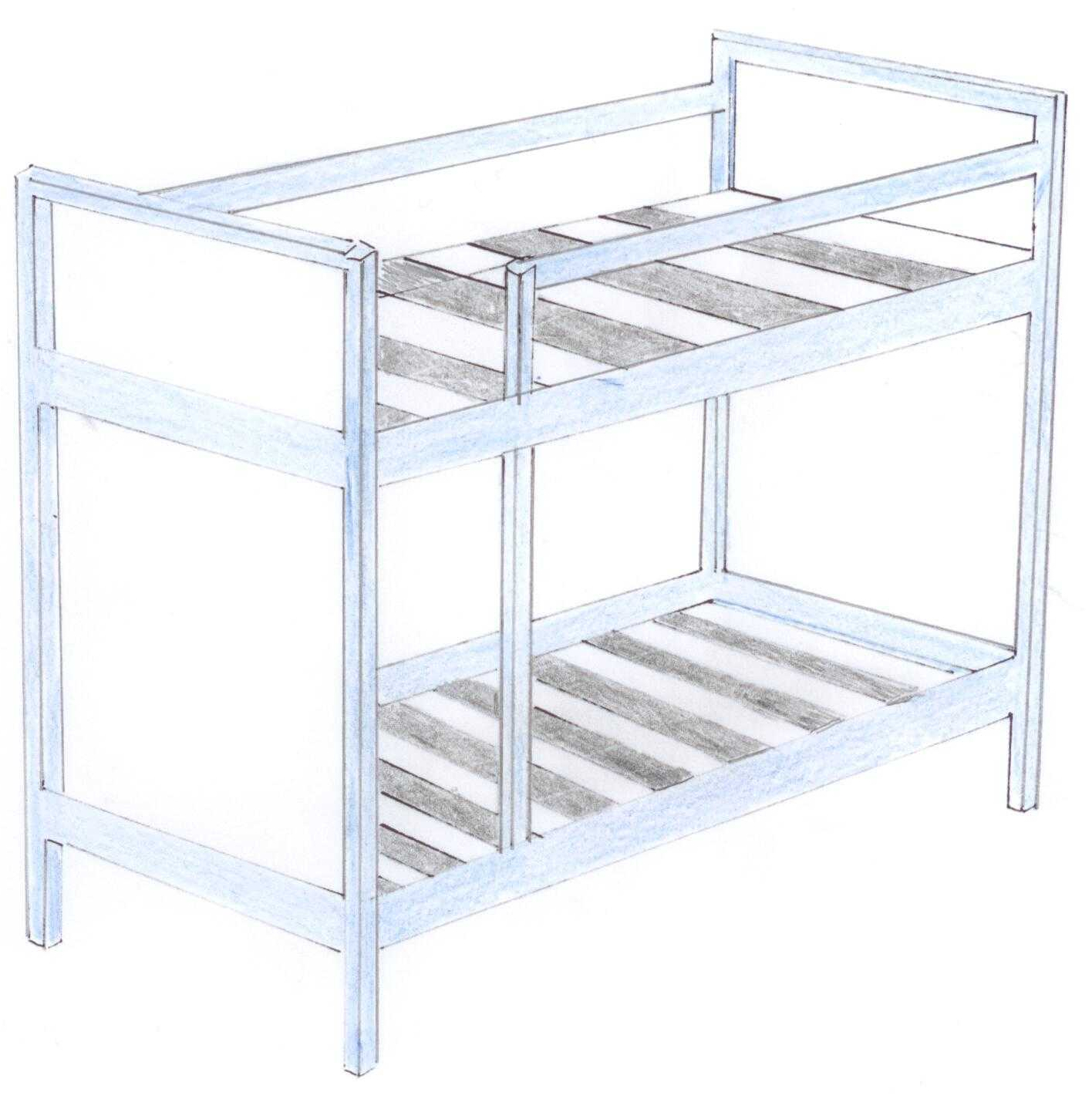
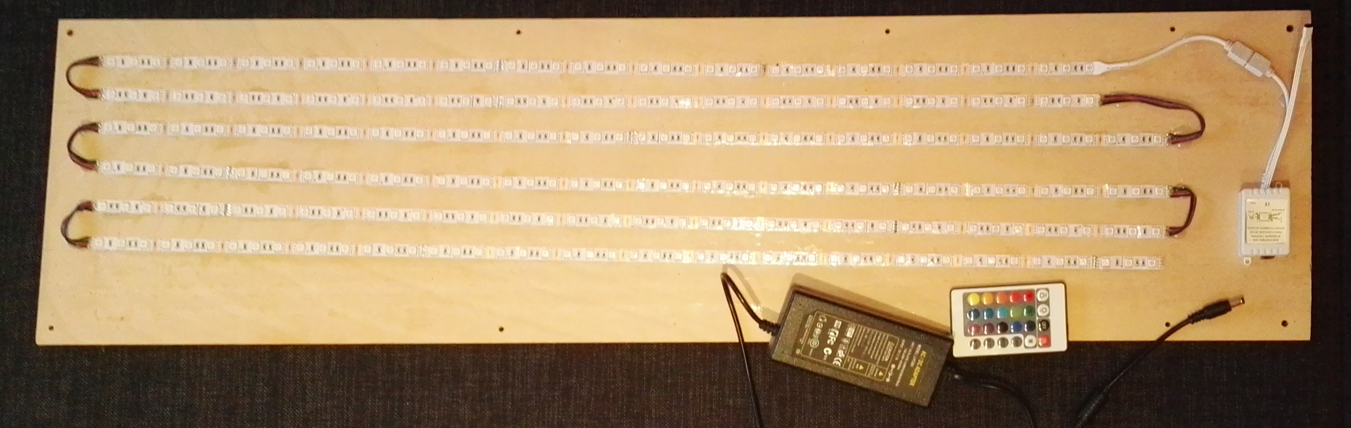
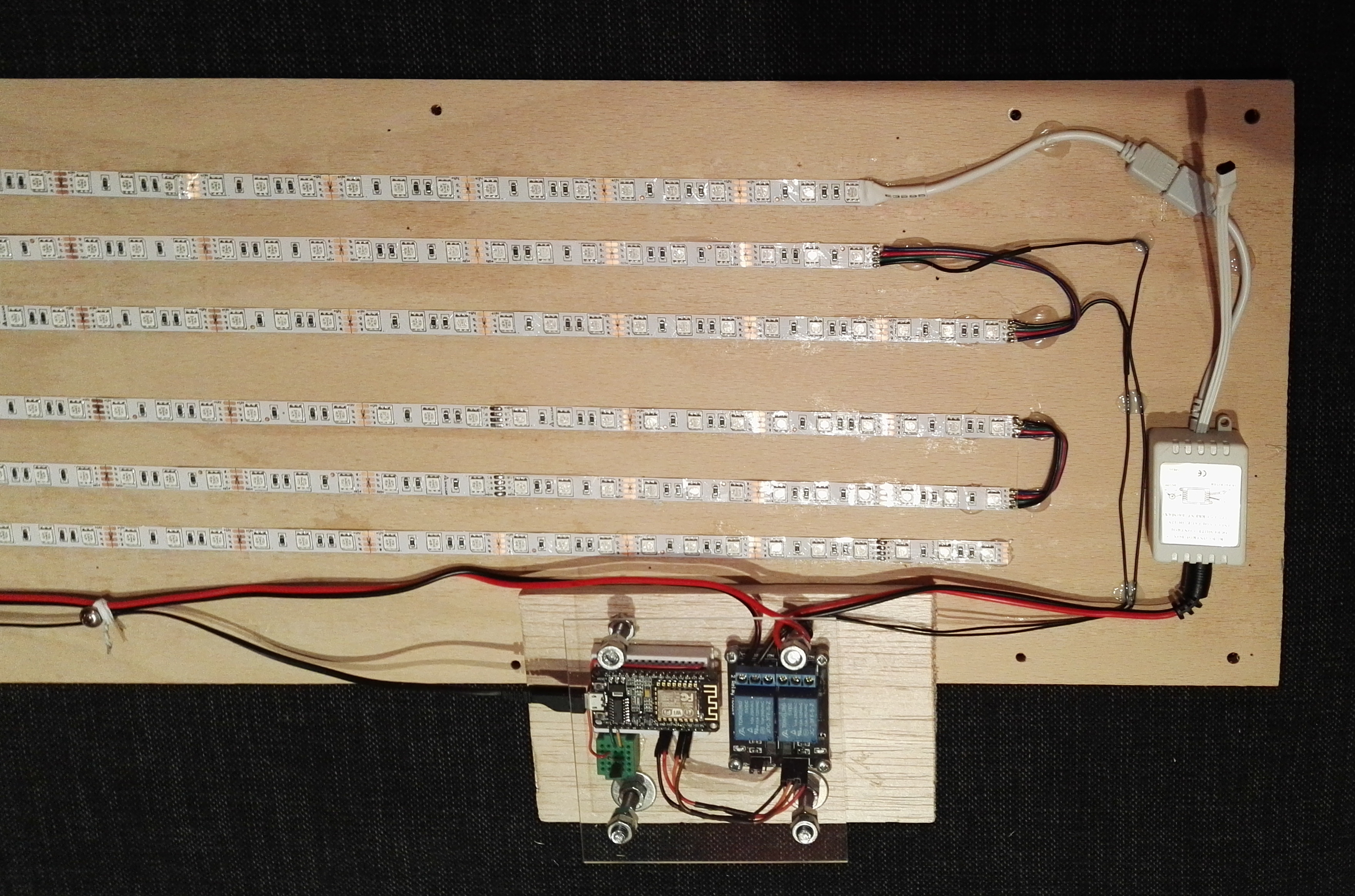
Rather than follow my friends sage advice I took a route less traveled.  The new plan was build a small control board that I could add to my existing “light fixture” so it would be possible to turn on and off the led strips via WiFi.

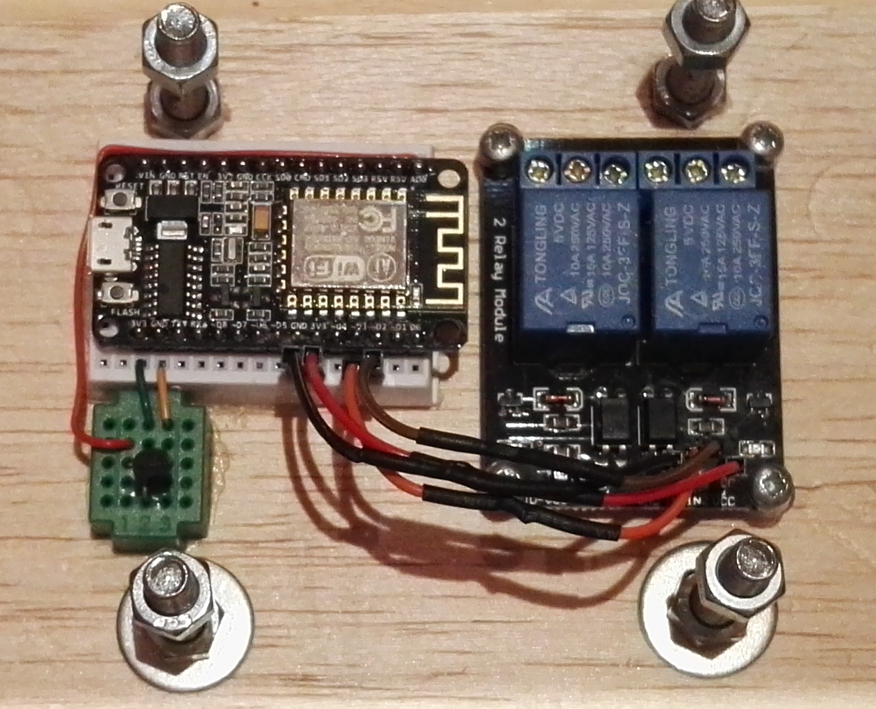
The parts I purchased to create my control board is as follows.

Item Name
WiFi capable
microcontroller
Elegiant Nodemcu Lua ESP8266 ESP 12E WiFi Development Board
Controllable relay
(ie switch)
2 Kanal 5V Relay Relais Module for Arduino 
Small bread board

TOOGOO(R) 5x Breadboard Steckboard

Tiny bread board

Experimentierboard 2×1,5cm

Temperature sensor

TMP 36 Temperatursensor

Development environment The open-source Arduino Software (IDE)

The WiFi device that I choose was not exactly an Arduino, but it was indeed a microprocessor that also had a 8266 WiFi board attached.  This board can also be programmed using the Arduino IDE.  Well, not without doing a small bit of configuration first.

Preparing the Arduino IDE

Unpacking the software

This actually depends on the platform that you are using and how you like to do things.  I will leave this as a an exercise to the user.  I happened to choose windows for this particular task as it was convenient.

I simply unpacked the IDE and added that directory to my path.

Configure the software

Once the software is unpacked or installed it is just a matter of running the IDE. All of the configuration will be done there.

In a nutshell this involves adding a new setup file into the preferences window and then using the Board Manager to install the new configuration.  This was briefly described at the following site

https://github.com/esp8266/arduino#installing-with-boards-manager

The first step is to add the configuration file in our preferences (file -> preferences).

arduino-preferences

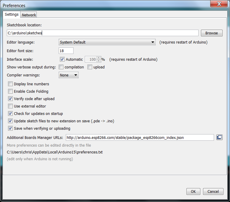
The Arduino IDE is a really nice bit of work.  You simply provide a JSON configuration file which really describes where a zip file with all of the code is and which additional board entries it supports.

Simply type this same JSON link into your web browser to see this setup. This is an excellent example of how to have a relatively generic IDE and yet have it fully configurable for supporting multiple setups.

http://arduino.esp8266.com/stable/package_esp8266com_index.json

The second step, once the JSON configuration is added to the preferences, is to go into the board manager and to select the configuration you want to install ( board “tools -> arduino/genuino uno -> boards manager …” )

arduino-boards-manager-install

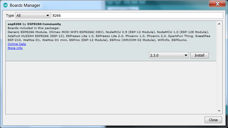
The install doesn’t actually do anything to the device itself but rather uses the JSON file to download the new configuration and libraries into the IDE.

For most people it isn’t so important where exactly the code is installed but for the curious it is not installed into the same directory as the rest of the IDE installation.  The new configuration is installed underneath the AppData directory for my user.

c:\Users\ralf\AppData\Local\Arduino15\packages

I would expect there is a similar mechanism on Linux, probably a directory in the users home directory.

Baby Steps

Being unfamiliar with the ESP8266, well the Arduino as well, I thought that I should learn to walk before I run so I did the hello world of the Arduino world.  This is typically some code to blink a led.  The good news was that my device actually had two leds on the board, it was just a matter of finding out how to access them.

I did have some initial difficulties, this was because I didn’t have any previous experience with the Arduino, the Arduino IDE, or the ESP8266.  If you look long enough on the internet you will find the answers to almost anything.  I did manage to find a number of different sites with information but perhaps the best starting place is on github.  They have a picture of the device, the descriptions of the pins as well as the circuit diagram.

The ESP8266 is open sourced so it is actually possible to create your own if you have the interest.

https://github.com/nodemcu/nodemcu-devkit

Although the Arduino community has a really good eco-system, I still had a few problems. I will not elaborate on most of my problems but one of them was my device was not explicitly listed in the list of board devices.

It turns out that isn’t really a big problem.  I ended up using the “Adafruit huzza” which proved to be compatible with my device although it is possible that some of the other devices in the boards manager would have also worked.

Once all of the rest of the configuration has been done, simply create a new project, enter the code and compile.

Blink code

1
2
3
4
5
6
7
8
9
10
11
12
13
14
15
16
17
18
19
20
21
#define ESP8266_LED1 16
#define ESP8266_LED2 2
 
void setup()
{
  Serial.begin(74880);
  Serial.println("begin");
  pinMode(ESP8266_LED1, OUTPUT);
  pinMode(ESP8266_LED2, OUTPUT);
}
 
void loop()
{
  Serial.println("in loop");
  digitalWrite(ESP8266_LED1, HIGH);
  digitalWrite(ESP8266_LED2, LOW);
  delay(500);
  digitalWrite(ESP8266_LED1, LOW);
  digitalWrite(ESP8266_LED2, HIGH);
  delay(500);
}

Uploading the code to the device is just as simple as pressing a button, but it is likely that you first need to go in and set the port the Arduino should use.  In my case the port had to be explicitly set.  The first time that I attached the device to the laptop with a USB cord a new communication port was created, in my case com6.

The upload process doesn’t take overly long and when it finishes, it will immediately start flashing the on-board leds.

The code should be fairly obvious to an Arduino developer, however, I will clarify a few points for the uninitiated.

code description
Serial.begin This configures the device to connect to the com port in order for the developer to see any output in the terminal window. The number given is the baud speed that will be used to communicate.

Note: This speed must match the speed set in your terminal window.

Serial.println This will print a message to the serial port.

Note: There is a Serial.print as well that works identically but does not do a carriage return line feed.

pinMode This sets the processor pin to either input or output.  In my examples it will be as output but it is possible to use the pin as part of a switch setup to get input from the user.

Note: OUTPUT is defined for you in the standard include files.

digitalWrite This changes the output value of the pin to either off or on.

Note: HIGH and LOW are defined for you in the standard include files.

delay This is a sleep method that will cause the device to sleep for the given number of milliseconds.

One thing that might not be intuitively obvious to the casual observer is why the baud speed of 74880 was chosen instead of the faster 115200.  This stems from my earlier difficulties using these tools.

The ESP8266 E12 board actually sets the port speed to 74880 upon restart.  If the terminal is set to 115200 instead, you will see some gibberish on the top of your terminal windows before the setup method of the program is called.  If you use the same speed as the default of the board then you see the startup message from the device along with any of your custom messages.

This entire article thus far is not very different from the run of the mill Arduino blink project.  Unfortunately the setup description took longer than I anticipated and thus the connection to the network via WiFi and controlling the device will be described in the final part,  Evolution LED Lighting – software solution.

Posted in programming, Setup From Scratch | Tagged , , | Comments Off on Evolution of LED Lighting – hardware and tools

Evolution of LED Lighting

When the children were really young they had a very tiny little nightlight.  It didn’t really give off all that much light but it was enough to keep the boys happy.  But nothing lasts forever and as it turns out they were growing up and that cute little light was for little kids.

This gave the perfect opportunity for me to get a large strip of RGB leds that could be mounted onto the end of bunk bed which would provide both the light and also provide a certain level of coolness.

Getting the setup was trivial as it is possible to purchase a led strip along with a power supply and remote control for switching the colors.

Version 1.0

bunkbeds

The setup was really simple as the led strip has a self adhesive tape on the back.

Pros

  • Can be installed within minutes

Cons

  • A bit bright
  • Gravity

It was super easy to mount the leds but gravity kept taking its toll.  They wouldn’t stay stuck on the board and in the end I had to get some tacks to help keep the led strip in place.  I could have used glue but considering that they were mounted vertically it would have been a pain to glue them on.

More than that, I was uncertain how long this solution would last and if permanent attachment to the wood was a good idea.

Version 2.0

The boys really did like the led solution but every time I came into their room during the day I saw a led strips that were hanging on for dear life.  Sure it worked but it didn’t look neat or professional.

In my mind the biggest problem with the existing solution was that it was attached to the bed.  There isn’t a lot of space between the bed and the wall.  If a problem were to actually occur with one of the led strips I would have to kneel in the corner between bed and wall to fix it.

The new plan was to create a small “light fixture” that could be mounted at the end of the bed. Because it is a light fixture I can take it to another room and work on it.  Doing this does have an additional level of effort as I did have to cut the strip into pieces and then to solder them back together once they were mounted to the board.

Led lighting version 2.0

The assembly wasn’t terribly challenging but perhaps my choice of wire for connecting the strips was less than optimal.  I had picked up a four wire extension core for led strips.  It was four wire extension cord that was red, green, blue and black.  The wires used matched the led strip but because they were all joined together like a flat cable and thus working with it was somewhat awkward.

Pros

  • Portable
  • Organized

Cons

  • Brighter than before
  • Gravity

However, Gravity has not been rescinded just because I have chosen to take a slightly different approach for mounting the led strips.  The adhesive tape still doesn’t hold well enough by itself and in the end I had to glue down the led strip.

The led solution is technically no brighter than before but they are now concentrated on a single board and they are now mounted lower on the bed across from a white wall.  This is still a good solution but the lights are actually too bright for nighttime lighting.

It was about this time that I was feeling just lazy enough that I thought perhaps I could just purchase some sort of solution that would let me control the led strip over my network.  I was hoping that this solution would allow me to programmatically control the leds both colors and power via WiFi.

Version 3.0

I couldn’t find exactly the type of control that I was looking for.  The question came up in my mind was just how difficult would it be to roll my own solution.

If you are a an electrical engineer coming up with custom electronics to control devices has most likely never been a problem.  For the rest of us, the mysteries of the electron and the catalog of parts that might be required can create a bit of a hurdle.

The good news is that 2016 is in the decade of the do-it-yourselfer.  There is an amazing amount of small general purposes electronics boards that can be quickly and easily connected together.

The electronic boards that are available range from micro-controller boards such as the Arduino but range up to full computers sporting multiple cores such as the Raspberry pi. Both of these devices provide pins that can be used to connect them to other external devices or chips to allow for novel expansion.

I am not a huge Arduino historian but it seems that it was previously possible to get a small addon board to allow it to connect via WiFi.  This was probably an incredible platform but it appears to have been supplanted with the ESP8266 board.  The ESP8266 board, or one of the numerous compatible boards, is essentially an Arduino with the WiFi chip on the same board.  This allows you to connect directly to the microcontroller via WiFi and then control whatever is connected to the I/O pins.

My solution is to use this new ESP8266  and a relay to control the led strip.  I purchased small board with two relays. A relay is just switch that can be used to control on and off electronically.

The change to the existing “lighting fixture” is to create a control board which routes the power through the relays which are controlled by the ESP8266.  I decided that the lowest overhead way to communicate with the ESP8266 was to send it commands via UDP packets.

Control board

The nice thing about this solution was that I could add the electronics to a small piece of wood and add it on as a controller board without having to completely redo the “lighting fixture”.

In order to add the control board to the “light fixture” I had to make two small changes to the original wiring.  The first change is to feed the ground of the main power through the first relay.  This makes it possible to cut off all the power to the leds, which is essentially an off switch.  The second change is to feel the ground wire to the relay which allows me to enable or disable the last four led strips.

This allows two strips to be lit and create some lighting for nighttime while still having the opportunity to turn on all the led strips.

Note: this just controls the power, the actual color selection or effects are still done via the remote control.

Led lighting version 3.0

Pros

  • Lights can be turned on and off via WiFi
  • Thermometer

Cons

  • Two power cords
  • Unable to control leds colors via WiFi

I will explain all of the construction and setup in the next part, Evolution of LED Lighting – hardware and tools.

Posted in Setup From Scratch | Tagged | Comments Off on Evolution of LED Lighting

nobody’s IT is perfect – real life shopping

Have you ever made a mistake at work?  Either it is small and your colleagues rib you about it or it is bigger and the boss yells at you.

What were you thinking?  Those crazy test case output went to real clients!!

I don’t usually mess up at work but when I do it does tend to be noticeable.  This is why I had to smile when I was recently window browsing at Amazon.com.

emacs-p2g-power

https://www.amazon.com/Emacs-P2G-6460P-ATX-Power-Supply/dp/B0012IP5E0/ref=sr_1_2?ie=UTF8&qid=1479294623&sr=8-2&keywords=emacs+p2g

It appears that the group that does the photos mixed up dangerous looking knifes with computer power supplies.  This error is not dangerous to life or limb but someone at Amazon obviously gets a chance to raise their exposure at work.

Oddly enough, a similar group at Amazon.de didn’t have any problems knowing the difference between a knife and a power supply as they did get the graphics correct.

amazon-de-power-supplies

However, not even the Germans get it correct all of the time.  I was surprised to see that while expanding the results from the p2g search a familiar image showed up.

sendero-obsession-cd

https://www.amazon.de/SENDERO-B-BAILEY-OBSESSION-Sendero-B-Bailey/dp/B0012IP5E0/ref=sr_1_16?ie=UTF8&qid=1479295692&sr=8-16&keywords=p2g

I guess the Germans are just as adventure loving as their American counterparts.  It would not surprise me if someone copied this image to a default within Amazon for testing and forgot to revert back to the original when the testing was finished.

Posted in Soapbox | Tagged | Comments Off on nobody’s IT is perfect – real life shopping

windows scripting

I was asked the other day if I could take over a task that was running on windows machine. The sentence was hardly out of my boss’s mouth when he said that “you unix guys don’t like windows though”. Well, he is correct but perhaps not for the same reasons that he thinks (who knows how bosses really think).

I am not a big windows fan because although you can write batch scripts they tend to be fairly simplistic. When I say simplistic, I mean what is possible right out of the box without downloading third party apps, installing something from MSDN or other power tools.

The “task” that I was being assigned was about processing some data files by type every few minutes. I thought about using a for loop to process every PNG file, followed by a loop to process every XML file but the more I thought about it the sillier that seemed to me.

Fortunately there is a way to examine the extension of a file even in windows. Simply add tilde and x when looking at the variable containing the filename.

In one way, it is very unix like. The comparisons are case sensitive which is a bit of a bummer on windows, where filenames are not really case sensitive. I did have to add a bit of extra logic to deal with both the upper and lower case extensions but in a more normal environment they should all be consistent.

1
2
3
4
5
6
7
8
9
10
11
12
13
14
15
16
17
18
19
20
21
22
23
24
25
26
27
@echo off
cd c:\temp\dosplay
FOR /f %%i in ('dir /l /b *.*') DO (
 
@echo .
@echo .
@echo ext %%~xi
@echo loop %%i
 
if "%%~xi" == ".PNG" (
start mspaint %%i
)
if "%%~xi" == ".png" (
start mspaint %%i
)
 
if "%%~xi" == ".XML" (
rem start notepad++ %%i
call vi %%i
)
if "%%~xi" == ".xml" (
rem start notepad++ %%i
call vi %%i
)
@echo .
@echo .
)

In this test I am using the start command to start executables but the call command when executing other batch scripts.

The second half of the assignment was to pause for a given amount of time between processing files. On Unix or Linux I would use the sleep command, which does not exist on windows. I was actually surprised to find out that there are two different alternatives which work just as well.

The first is the timeout command. It is actually the same as the sleep command but it actually counts down on the screen.

c:\temp\dosplay>timeout 10 > output.txt
c:\temp\dosplay>type output.txt
Gewartet wird 10 Sekunden. Weiter mit beliebiger Taste. 

If this is ok in your output then just redirect this output in the same way as any other commands. When this is inacceptable them simply redirect the output to nul.

timeout 10 >nul

The second method is actually essentially the same. The waitfor command will wait for a certain about of time before simply resuming.

c:\temp\dosplay>waitfor /t 10 pause
FEHLER: Beim Warten auf "pause" wurde das Zeitlimit überschritten.

This example will wait for the pause to finish. It actually won’t finish nor will pressing any keys cause it to continue. It will simply will wait for the number of seconds given and then generate an error. It is possible to redirect this error to the nul output device as well.

rem waitfor /t 10 pause >nul
Posted in Command line, programming | Tagged , | Comments Off on windows scripting

Machine generation of PDF files the easy way – final piece

This is essentially a refinement of the previous steps. I have added a lot of new list data but instead of being limited to what political party they are in or even if they like to party, I have extended this a bit. The final result will generate a form and will look like this.

data7

Now “party” data field is actually much more generic. It can be whatever is described in the xml file itself.

1
2
3
4
5
6
<being>
   <first> Hooch  </first>
   <last>  </last>
   <party> Dogue de Bordeaux </party>
   <additionaldesc> breed </additionaldesc>
</being>

Note: Lazy programmer syndrome. The proper thing to do would have been to rename the party field to a more neutral name.

Thus it is possible to use the additionaldesc field to contain a better name for that cell.

It really isn’t necessary but I have added a header to each list. What is in each header is hard-coded but it does serve to provide an interesting reminder about the support that is provided. Simply by defining this table-header it will be displayed each time the table is broken by a page break.

Also the footer has been modified to display a page number. Generating a page number is not difficult but it also provides the trick to display the total number of pages as well. This is neat because the xslt script is data driven, it has no idea how many pages exist when it is run.

The second change to the footer probably seems unnecessary at first glance. I have added a table so I can display my text left justified and the page number right justified. Normally you would think that simply adding the text-align to the block would be enough, and in one sense it is. When I first did this example it kinda worked. The text was left justified on one line and the page number was right justified on the next line. In order to have both of these pieces of text on the same line I needed to create a table in the footer.

There is really a lot more that could be done using XSL-FO but that will have to be left to another time.

Download source and pdf for this example

Download everything.

Posted in programming | Tagged , , , | Comments Off on Machine generation of PDF files the easy way – final piece

Machine generation of PDF files the easy way – part VI

The entire example report up until this point has been nice with a cool feature or two but terribly unrealistic. It is important to have the data in mind when creating the form but the form that I have created is not good for much more than a simple laundry list.

The sixth example result will generate a form and will look like this.

data6

The big change for this step is that rather than having a single set of data where all the items are identical, I slightly have changed the data structure to support multiple lists.

1
2
3
4
5
6
7
8
9
10
11
12
13
14
15
16
17
18
19
20
21
22
23
24
25
26
27
28
29
30
31
32
33
34
35
36
37
38
<xmlroottag>
 
   <beings>
     <listtype>presidents </listtype>
     <being>
        <first> Robert </first>
        <last> Kennedy </last>
        <party> Dem </party>
     </being>
     <being>
        <first> George </first>
        <last> Bush </last>
        <party> Rep </party>
     </being>
     ...
   </beings>
 
   <beings>
     <listtype>Rock Stars </listtype>
     <being>
        <first> Dave </first>
        <last> Chappelle </last>
        <party> Yup </party>
     </being>
     <being>
        <first> Rod </first>
        <last> Stewart </last>
        <party> Yup </party>
     </being>
     <being>
        <first>  Izzy </first>
        <last>  Stradlin  </last>
        <party> Ya </party>
     </being>
     ...
   </beings>
 
</xmlroottag>

Most of the xslt script remains the same when compared to the previous step. The difference is that we have a template for beings. This makes it really easy to create our table. The table should be full of records of type being and we have a template for generating each being. Thus we simply move the table declaration in to the beings template.

The only non-obvious part of this is why is there an apply-templates? The purpose of this is identical to the apply-templates in the region-body. It will start from the current position and for each xslt object at that level will evaluated against the existing templates.

Thus we have the apply-templates in the region body to cause the “beings” template to be executed (for each group of beings) and once we are in the beings template, the apply-templates causes each xslt object to be evaluated with the existing templates. This is what causes each being to be processed with the being template.

1
2
3
4
5
6
7
8
9
10
11
12
13
14
15
16
17
18
19
20
21
22
23
24
25
26
27
28
29
30
<xsl:template match="beings">
    <fo:block font-size="16pt" font-weight="bold" space-after="2mm" space-before="5mm" >List of <xsl:value-of select="listtype"/>
    </fo:block>
 
    <fo:block font-size="10pt">
 
        <fo:table table-layout="fixed" width="8cm">
            <fo:table-column column-width="proportional-column-width(70)" />
            <fo:table-column column-width="proportional-column-width(30)" />
              <fo:table-header>
                <fo:table-row >
                  <fo:table-cell border-collapse="collapse" border-style="solid" border-width=".1mm" text-align="left" >
                     <fo:block font-size="10pt" font-weight="bold" background-color="lightgray" >Object</fo:block>
                  </fo:table-cell>
                  <fo:table-cell border-collapse="collapse" border-style="solid" border-width=".1mm" text-align="left" >
                     <fo:block font-size="10pt" font-weight="bold" background-color="lightgray" >Attr.</fo:block>
                  </fo:table-cell>
                </fo:table-row >
              </fo:table-header>
            <fo:table-body>
 
               <xsl:apply-templates />
 
            </fo:table-body>
        </fo:table>
 
        <fo:block space-before="5mm"> thats all folks! </fo:block>
 
    </fo:block>
</xsl:template>

The actual “being” records are all identical but they are all part of a beings structure. There are no limit to the number of “being” records but they are now all grouped together. Part of this group is the listtype field. So each group of beings could still be presidents or of different types of people or objects.

I have decided that the most natural fit would be to have a data file with both presidents and rock singers. How this looks actually is quite similar to the output in the previous step except that it is now possible to have an infinite number of beings in an infinite number of groups. Thus at a later point the program which creates this data file could add superheros or politicians without needing to amend the xslt script at all.

You need to either think a lot about this or look at the code to realize that there is now an additional listtype template. This template was created so the listtype element could be evaluated. When a template does not exist, then FOP will output the value. Having the listtype value randomly output to the form is not what is desired which is why the listtype template exists but doesn’t really contain a body. This was necessary because I needed the listtype value but I didn’t want to have a template to output the listtype.


Download source and pdf for this example

The next set of changes for this can be found in the final part.

Posted in programming | Tagged , , , | Comments Off on Machine generation of PDF files the easy way – part VI

Machine generation of PDF files the easy way – part V

While preparing these articles I didn’t have an overarching goal.  I probably should have began with the header and footer and kept that through all examples but I changed my focus while writing this all up.

This fifth example just combines both the header and footer from step 2 with the results from my previous step. The final result will generate a form and will look like this.

data5

It really does look good even though there are a few little things that could be improved. They will be corrected in the next step.


Download source and pdf for this example

The next set of changes for this can be found in part VI.

Posted in programming | Tagged , , , | Comments Off on Machine generation of PDF files the easy way – part V

Machine generation of PDF files the easy way – part IV

This fourth example will extend upon my previous XSL-FO script to convert the list from a table with a few boxes into more of a polished form. The final result will generate a form and will look like this.

data4You are only really limited to your imagination for a lot of XSL-FO. It is possible to change how the pages are laid out, types of headers, types of footers, orientation of the pages, various margins, add additional fonts or even add graphics.

One of the small things that really makes forms look like forms is the ability to put a small description in each of the cells. If the form is machine printed it will look good but if the form is for the user to fill in, it is a necessary description.

The only change is to add these small descriptions for each cell of this form. Conceptually, what you do is to have a table within each cell where the description is very small text and the field value is a normal sized text.

This isn’t the only way to achieve this result but to add this to an existing form is fairly mechanical in nature. This method causes all of the descriptions to look the same and be located the same spot in each cell.

You could fool around with fonts and sizes but getting things to line up the way you want without using an inner table would be challenging.

Simple cell

1
2
3
4
5
6
7
8
9
10
11
12
13
14
15
16
<xsl:template match="person">
    <fo:table-row >
       <fo:table-cell font-weight="bold" border-collapse="collapse" border-style="solid" border-width=".1mm" text-align="left" padding="1mm" >
           <fo:block>
           <xsl:value-of select="first"/>
           <xsl:value-of select="last"/>
           </fo:block>
       </fo:table-cell >
       <fo:table-cell
 
           ...
           second cell left off for clarity
 
       </fo:table-cell>
    </fo:table-row >
</xsl:template>

Cell with description

1
2
3
4
5
6
7
8
9
10
11
12
13
14
15
16
17
18
19
20
21
22
23
24
25
26
27
28
29
30
31
32
33
34
35
36
37
38
39
40
<xsl:template match="person">
    <fo:table-row >
       <fo:table-cell border-collapse="collapse" border-style="solid" border-width=".1mm" text-align="left" padding="1mm" >
 
           <fo:block font-family="Helvetica" font-size="10pt" >
            <fo:table table-layout="fixed" width="100%" >
              <fo:table-column column-width="proportional-column-width(100)" />
              <fo:table-body>
                  <fo:table-row>
                    <fo:table-cell >
 
                        <fo:block font-family="Courier" font-weight="bold" font-size="6pt" > Name
                        </fo:block>
 
                    </fo:table-cell>
                  </fo:table-row>
 
                  <fo:table-row>
                    <fo:table-cell >
 
                        <fo:block>
                        <xsl:value-of select="first"/>
                        <xsl:value-of select="last"/>
                        </fo:block>
 
                    </fo:table-cell>
                  </fo:table-row>
              </fo:table-body>
            </fo:table>
           </fo:block>
 
       </fo:table-cell >
       <fo:table-cell border-collapse="collapse" border-style="solid" border-width=".1mm" text-align="left" padding="1mm" >
 
           ...
           second cell left off for clarity
 
       </fo:table-cell >
    </fo:table-row >
</xsl:template>

There is virtually really no changes over the cell with border that was added in the previous step. Well one tiny attribute change. The attribute padding was added to to put a very tiny space between the values provided and the edges of their cell. Simply put adding padding=”.1mm” adds a .1mm margin around the innermost cell.

Adding niceties of this type do make for a polished product but the users cannot appreciate the effort put in. It will be quite visible when maintaining the xslt code.


Download source and pdf for this example

The next set of changes for this can be found in part V.

Posted in programming | Tagged , , , | Comments Off on Machine generation of PDF files the easy way – part IV